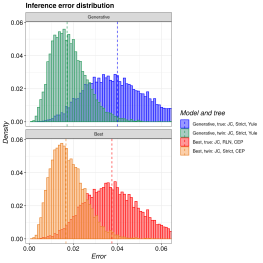
pirouette is an R package that estimates the error BEAST2 makes from a given
phylogeny. This phylogeny can be created using any (non-BEAST) speciation model,
for example the Protracted Birth-Death or Multiple-Birth-Death models.
Bilderbeek, RJC, Laudanno, G, Etienne, RS. Quantifying the impact of an inference model in Bayesian phylogenetics. Methods Ecol Evol. 2020; 00: 1– 8. https://doi.org/10.1111/2041-210X.13514
AppointDent is a full-stack web application that
allows residents of Sweden manage their dentist appointments, as well as a tool
for dentists to organize their work. The system, internally, relies on a
distributed system infrastructure that combines various architectural
styles, namely microservices, publish-subscribe and client-server.
AppointDent is a system that allows residents of Sweden to book dentist
appointments. A user can find available times and see the dentist on an
integrated map.
AppointDent allows users to book appointments, cancel them, as well as receive
notifications about their bookings. The dentists in our system make use of a
calendar to navigate their appointments and manage their availability.
The solution is based on a distributed system infrastructure that combines
various architectural styles, namely microservices, publish-subscribe
and client-server.
The only technology that is utilized in building and running all services, APIGateway (server), the client, and stress-testing is Node.js. Our project makes use of version 18.x.x. Ensure that you have a compatible version installed on your machine (we recommend 18.12.2). Read more about Node.js (and npm) here.
For the Solid.js framework, we recommend using npm as the package manager and installing the version from the package.json file with Vite.js as the build tool.
Alternatively, install ^1.7.8 version of Solid.js (+^4.4.5 of Vite.js) with the help of your preferred package manager/environment utility.
In terms of stress-testing the system, we recommend using the latest version of k6. Navigate to stress-testing for more information.
Installation, Setup, and Running
This repository utilizes a monorepo structure, where the individual sub-folders represent a particular component of the system, wherein each component has its own README.md file.
The file contains the instructions on how to install all dependencies, it explains the structure of the directory, and it lists all the available scripts (with possible clarifications).
The following is a list of the available sub-folders:
services/session-service: a central service that handles all sessions of the users to enforce authentication and authorization.
stress-testing: a folder that contains the scripts that are used to stress-test the system at a high load.
Note
The services are not meant to be run individually, but rather as a part of
the server application. They can be run individually for testing purposes
or for the ease of development.
Architecture
Our system is a distributed one and we have therefore decided to use a
Microservices-based architecture. This means that different services are to
be installed on different computers and are completely independent. The MQTT
(Message Queue Telemetry Transport) protocol is implemented as the primary
communication utility between the individual services of our system.
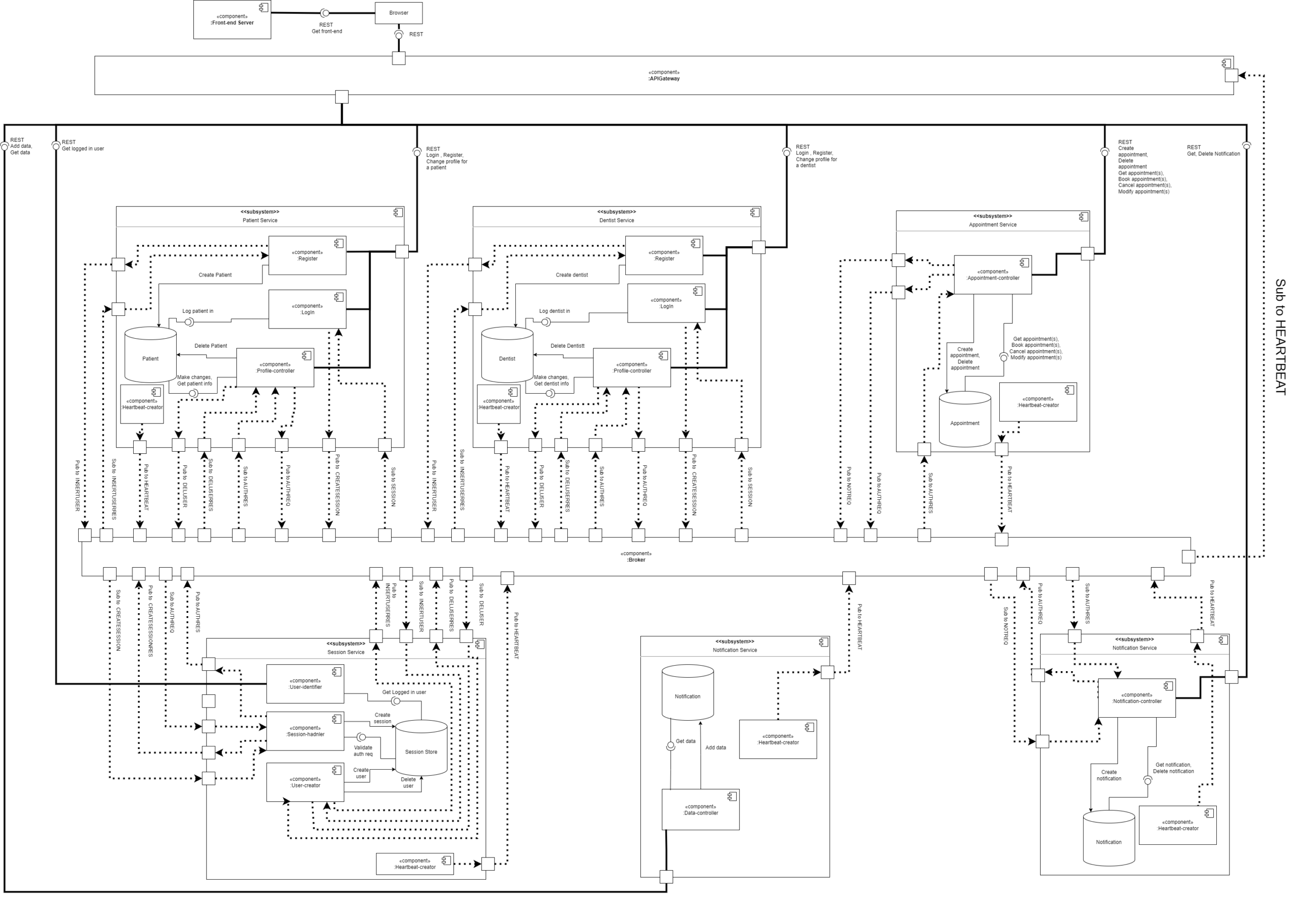
See our Component Diagram for a detailed overview of the
architecture in use.
Furthermore, several other decisions that have a substantial
impact on the architecture that the team members dealt with during the project’s
development may be traced with the ADRs.
System’s Overview
The following section aims to provide an overview of the system’s
architecture, as well as the deployment strategy. The individual diagrams
can observed when clicking on the dropdowns.
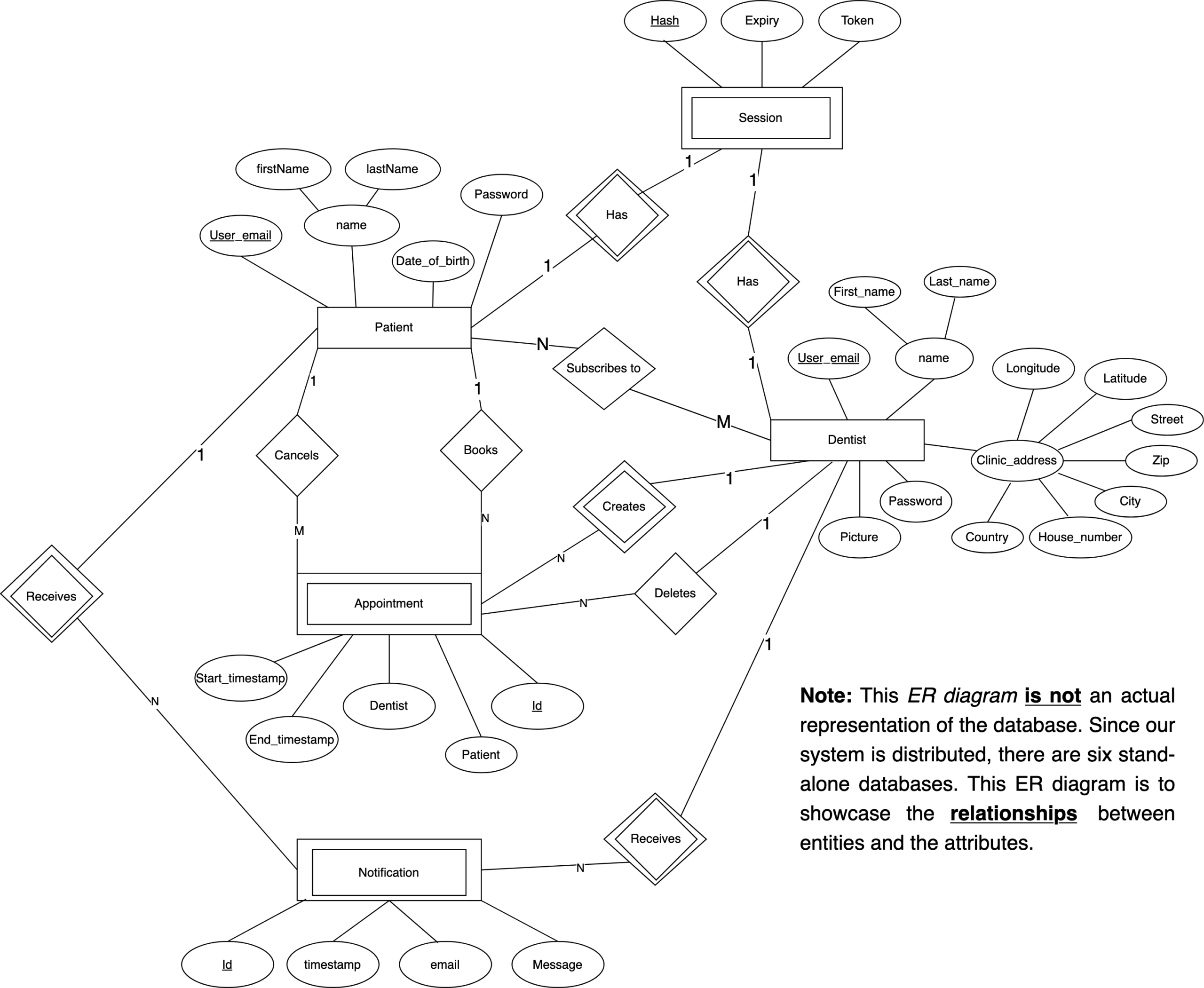
1. Entity Relationship (ER) Diagram
2. Component Diagram
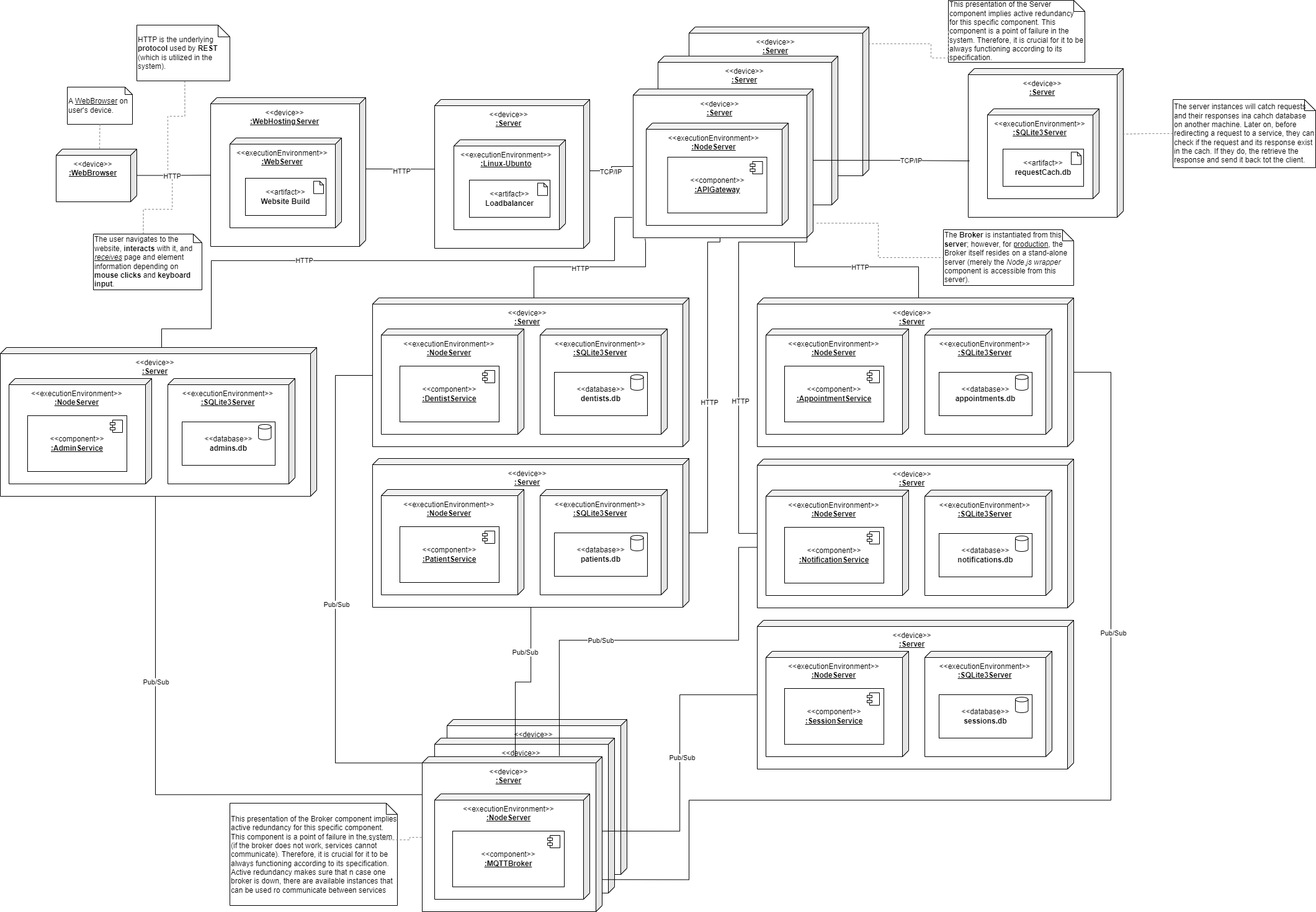
3. Deployment Diagram
Continuous Integration
The development team made use of the continuous integration (CI) testing
practice to improve the development process model (which was Scrum) that was
used in the development of the system. This allowed the team to continuously
build and test the code in order to prevent pushing defective code into the
main branch.
The team made use of Postman as means of integration testing of the back-end
and the database of the system. Moreover, the team made use of static analysis
(ESLint) to make sure good quality and readable code with no syntax bug is
pushed into the main branch.
In order to make use of CI, the team made use of GitLab’s CI/CD feature. The
gitlab-ci.yml
file contains the instructions that are used by GitLab to run
Postman tests, statically analyze code, and build the system.
Important
The project was initially developed on the GitLab platform, but was later
migrated to GitHub. However, the CI/CD pipeline was not migrated yet, hence
the pipeline is not functional on GitHub.
Development team
The project has been developed over the course of 10 weeks by the following:
AppointDent is a full-stack web application that
allows residents of Sweden manage their dentist appointments, as well as a tool
for dentists to organize their work. The system, internally, relies on a
distributed system infrastructure that combines various architectural
styles, namely microservices, publish-subscribe and client-server.
AppointDent is a system that allows residents of Sweden to book dentist
appointments. A user can find available times and see the dentist on an
integrated map.
AppointDent allows users to book appointments, cancel them, as well as receive
notifications about their bookings. The dentists in our system make use of a
calendar to navigate their appointments and manage their availability.
The solution is based on a distributed system infrastructure that combines
various architectural styles, namely microservices, publish-subscribe
and client-server.
The only technology that is utilized in building and running all services, APIGateway (server), the client, and stress-testing is Node.js. Our project makes use of version 18.x.x. Ensure that you have a compatible version installed on your machine (we recommend 18.12.2). Read more about Node.js (and npm) here.
For the Solid.js framework, we recommend using npm as the package manager and installing the version from the package.json file with Vite.js as the build tool.
Alternatively, install ^1.7.8 version of Solid.js (+^4.4.5 of Vite.js) with the help of your preferred package manager/environment utility.
In terms of stress-testing the system, we recommend using the latest version of k6. Navigate to stress-testing for more information.
Installation, Setup, and Running
This repository utilizes a monorepo structure, where the individual sub-folders represent a particular component of the system, wherein each component has its own README.md file.
The file contains the instructions on how to install all dependencies, it explains the structure of the directory, and it lists all the available scripts (with possible clarifications).
The following is a list of the available sub-folders:
services/session-service: a central service that handles all sessions of the users to enforce authentication and authorization.
stress-testing: a folder that contains the scripts that are used to stress-test the system at a high load.
Note
The services are not meant to be run individually, but rather as a part of
the server application. They can be run individually for testing purposes
or for the ease of development.
Architecture
Our system is a distributed one and we have therefore decided to use a
Microservices-based architecture. This means that different services are to
be installed on different computers and are completely independent. The MQTT
(Message Queue Telemetry Transport) protocol is implemented as the primary
communication utility between the individual services of our system.
See our Component Diagram for a detailed overview of the
architecture in use.
Furthermore, several other decisions that have a substantial
impact on the architecture that the team members dealt with during the project’s
development may be traced with the ADRs.
System’s Overview
The following section aims to provide an overview of the system’s
architecture, as well as the deployment strategy. The individual diagrams
can observed when clicking on the dropdowns.
1. Entity Relationship (ER) Diagram
2. Component Diagram
3. Deployment Diagram
Continuous Integration
The development team made use of the continuous integration (CI) testing
practice to improve the development process model (which was Scrum) that was
used in the development of the system. This allowed the team to continuously
build and test the code in order to prevent pushing defective code into the
main branch.
The team made use of Postman as means of integration testing of the back-end
and the database of the system. Moreover, the team made use of static analysis
(ESLint) to make sure good quality and readable code with no syntax bug is
pushed into the main branch.
In order to make use of CI, the team made use of GitLab’s CI/CD feature. The
gitlab-ci.yml
file contains the instructions that are used by GitLab to run
Postman tests, statically analyze code, and build the system.
Important
The project was initially developed on the GitLab platform, but was later
migrated to GitHub. However, the CI/CD pipeline was not migrated yet, hence
the pipeline is not functional on GitHub.
Development team
The project has been developed over the course of 10 weeks by the following:
This is a simple script that will erase users, their media, and redact all their events from a Synapse server based on specific criteria:
not an admin
not a guest
not deactivated
not contain a specific string in their MXID
not older than a specific threshold in days
It was developed for the etke.cc demo server for the purpose of cleaning up the user database.
Another purpose of this repo is to be a test stand for migrating our gitlab repos to github
Don’t expect this to be a full-featured tool, it’s just a simple script that does one thing.
Configuration
Configuration is done via environment variables (.env file is supported as well). The following variables are supported:
SUAE_HOST – Synapse server host, e.g. https://matrix.example.com (without trailing slash)
SUAE_TOKEN – Synapse homeserver admin token
SUAE_PREFIXES – Space-separated list of additional MXID prefixes that should be excluded from deletion
SUAE_TTL – Maximum age of the user in days, users younger than this value will not be deleted
SUAE_DRYRUN – If set to true, the script will only print the list of users that would be deleted. You WANT to run it in dry-run mode first to make sure you’re not deleting the wrong users.
Check .env.example for an example configuration.
Usage
# if you want to run it with docker, do this
$ docker run --rm --env-file .env ghcr.io/etkecc/synapse-user-autoerase
# if you have binary, run it like this
$ synapse-user-auto-erase
# if you want to run from source
$ just run
⚠️ NOTE: This is a fairly new project. Functionally everything is working on tested Nerves systems.
What Is This?
NervesFlutterSupport is the base library for running Flutter based UI applications on Nerves devices.
Overview
NervesFlutterSupport contains the following components:
Pre-compiled and patched runtime libraries for various dependencies. (See builder/ for more info.)
Including a pre-compiled version of Sony’s open source Flutter Embedder.
A pair of Mix Release Steps that can be included in your existing Mix project.
Takes care of downloading the Flutter embedder and runtime libraries.
Will automatically compile your Flutter project using the gen_snapshot tool and output an AOT build.
Will help copy the runtime artifacts from the dependency source directory to the release directory at compile time.
NervesFlutterSupport.Flutter.Engine – A module to create a Muontrap child_spec for running the embedder.
NervesFlutterSupport.Udev – (Automatically started for you) A module that ensure eudevd is running for input devices to function properly.
Tested Platforms
NervesFlutterSupport has been tested on the following platforms:
Raspberry Pi 4
Raspberry Pi 5
However it should be noted that any aarch64 based Nerves System should be compatible with this library.
Please file any issues if you run into any problems with your ARM64 platform. We also welcome Buildroot config contributions for other platforms.
Getting Started
Currently we only support Linux and macOS hosts when building firmware. Windows users should use WSL.
If you are a macOS user, please ensure you have docker installed!
Install Flutter. See the top of this readme file for which version to use. (Flutter versions may change with Hex package versions!)
Create a new Flutter app in your Mix project using: flutter create flutter_app.
Add this package to your deps in mix.exs.
Add the release steps to your existing firmware’s steps::
steps: [&Nerves.Release.init/1,&NervesFlutterSupport.InstallRuntime.run/1,# REQUIRED!! - Add this to install runtime artifacts into the release!&NervesFlutterSupport.BuildFlutterApp.run/1,# OPTIONAL - Add this if you want to auto-compile a flutter app!:assemble],
Run mix firmware as you normally would, if all is well, you should see you Flutter app build and emit a bundle into your priv/ directory.
To run the Flutter app you can add the following to your Application or Supervisor children:
# With no options, your Flutter app bundle is expreted to be in `priv/flutter_app`NervesFlutterSupport.Flutter.Engine.create_child(app_name: :my_flutter_app,)
NervesFlutterExample is a basic Flutter + Nerves firmware for :rpi4 and :rpi5 targets. It uses
gRPC and Protobufs to communicate between the Nerves firmware code and the Dart Flutter application.
Warning! This project is very old at this point! Some of the ideas may be fine would not recommend you use it as a modern reference
React/Redux/Thunk – babel/webpack2
This project describes the process of connecting a bank account to your own Account. So when you log in you are taken to the choose a bank account, then as one bank is chosen you are asked to finish adding login data to complete login in. As the form is send you are send to a page where your latest bank transactions data is displayed.
Installation
Execute npm install to install dependencies
Usage
Execute npm run dev to run the development server on localhost:8080
or
Execute npm run prod to run the production server. For testing use localhost:4000
What’s done
CSS Approach: I have changed boilerplate to add post-css and css-modules. Also, added redux-devtools to be able to work with redux data in a development setting. See wiki pages CSS-Methodology
Implement a bank selection that persists the login screen: Bank selection is done by saving the user selected bank to the redux store. To paint the buttons: We map through an inline array calling a BankListItem component to render on each iterate, passing th eprops necesary for each button. BankListItem resides on the components folder and it just renders the bank images as buttons. Each button will have an onClick handler triggering the action to save the bank name to the redux store when triggered. Special carefulness have been made into no binding but instead using arrow functions when declaring handlers within react classes. See BankListItem while the ChooseBankPage container is here.
Implement sensible form validation: I have implemented a HOC that wraps the form component and that deals with form state and actions present in the form. Additionally I have detached actual validations from the form state so the user only needs to define the validation rules and pass them onto the validation’s HOC as a config object. So these are not hard-coded into the HOC. See more on the wiki pages Form-Validation
The container component is LoginPage.js and the HOC is called Revalidation.js, both are found here and the login form is here.
Build the transactions screen using the api end-pointlocalhost:3000/api/transactions: First, a server have been implemented to serve json from the data folder, enabling CORS to handle calls to localhost. I this sense I use the concurrently library to run both the development server and the API at the same time, with just one script. See scripts on the package.json file here and the dev API serverhere
Then, creating the views is just a mater of rendering the actual components defined on the components/statements folder. In more detail, the statementPage container renders AccDetails and ListView components, also declares and passes down to ListView the renderRow markup. Detaching the renderRow from the ListView permits us to reuse the ListView in any other part of the app. From there on, ListView maps through the passed props (renderRow) which calls and pains a row for each iterate of the map function.
See StatementPagehere ListView and ListRow are here
Another thing is that I am using selectors for the first time in this app to prepare and digest data before passing it to the rendering component. See getTransactions selector in the reducers/bank reducer file. What the getTransactions selector does is prepare and return an array of transactions by id and the actual collection of transactions. Later on, the ListView component will iterate through the array of ids, taking from the collection the current transaction and rendering the row with the data.
Selectors in the reducers/bank code is here
Fix and expand the unit tests: I am testing presentational components by creating snapshops. Also, testing event handlers and state where appropriate. On unit tests, there are behavioral tests for actions and reducers. See wiki pages Tests for more on this.
Login and authentication: I have used a HOC component that wraps the private routes and confirms the loggedIn state of user.
See wiki pages Login-and-Authentication
Contributing
Fork it!
Create your feature branch: git checkout -b my-new-feature
Commit your changes: git commit -am 'Add some feature'
Push to the branch: git push origin my-new-feature
In this project, you will use what you’ve learned about deep neural networks and convolutional neural networks to classify traffic signs. You will train a model so it can decode traffic signs from natural images by using the German Traffic Sign Dataset. After the model is trained, you will then test your model program on new images of traffic signs you find on the web, or, if you’re feeling adventurous pictures of traffic signs you find locally!
Dependencies
This project requires Python 3.5 and the following Python libraries installed:
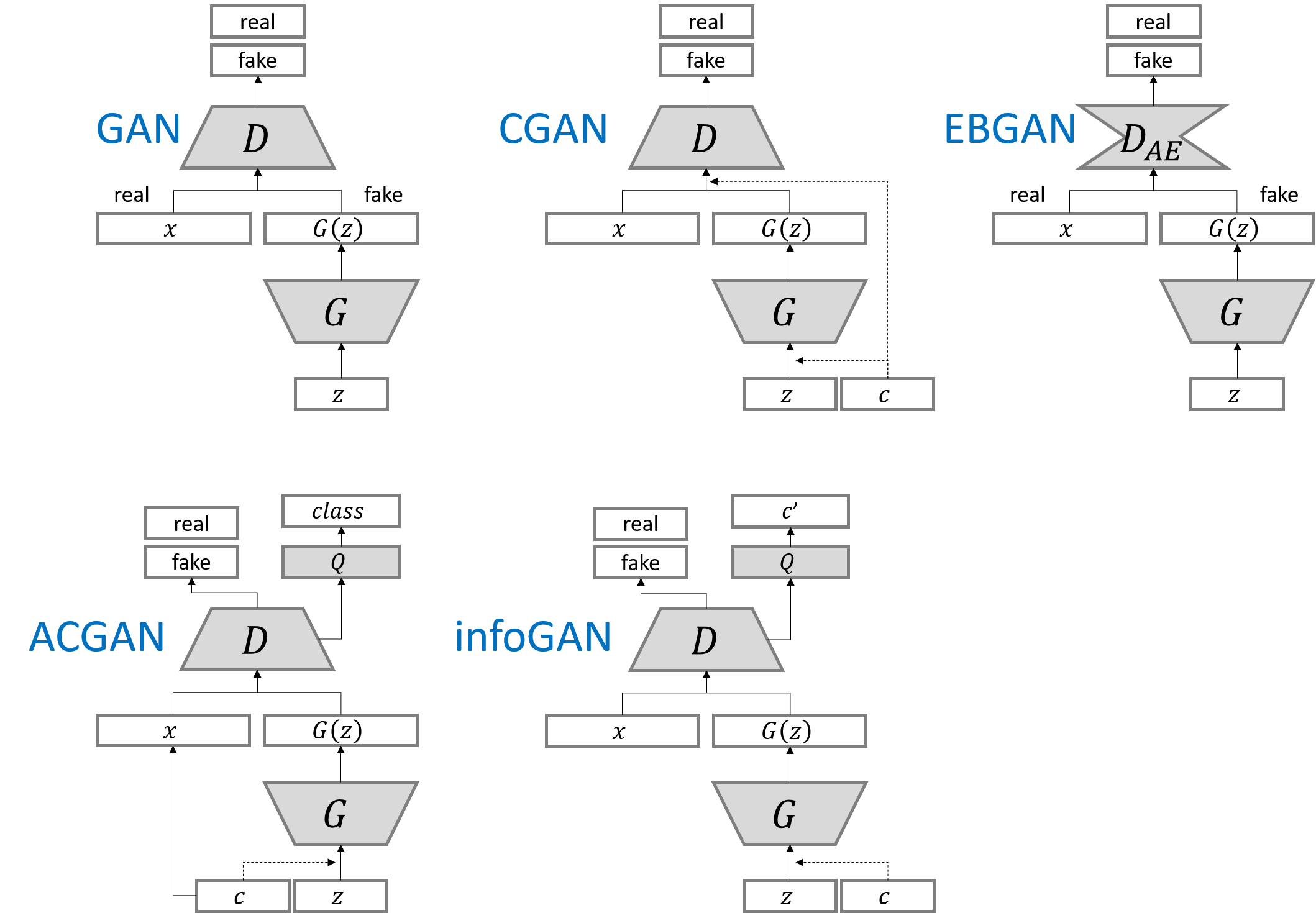
Network architecture of generator and discriminator is the exaclty sames as in infoGAN paper.
For fair comparison of core ideas in all gan variants, all implementations for network architecture are kept same except EBGAN and BEGAN. Small modification is made for EBGAN/BEGAN, since those adopt auto-encoder strucutre for discriminator. But I tried to keep the capacity of discirminator.
The following results can be reproduced with command:
All results are generated from the fixed noise vector.
Name
Epoch 1
Epoch 25
Epoch 50
GIF
GAN
LSGAN
WGAN
WGAN_GP
DRAGAN
EBGAN
BEGAN
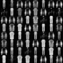
Conditional generation
Each row has the same noise vector and each column has the same label condition.
Name
Epoch 1
Epoch 25
Epoch 50
GIF
CGAN
ACGAN
infoGAN
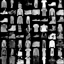
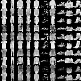
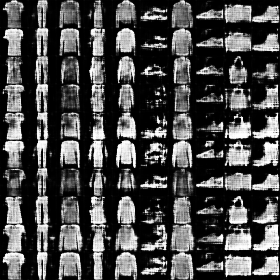
InfoGAN : Manipulating two continous codes
All results have the same noise vector and label condition, but have different continous vector.
Name
Epoch 1
Epoch 25
Epoch 50
GIF
infoGAN
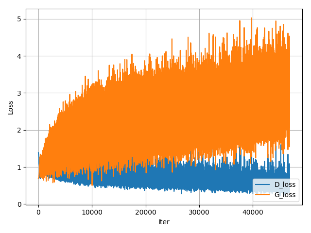
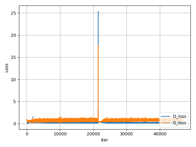
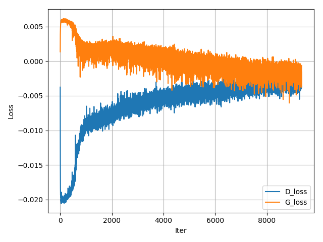
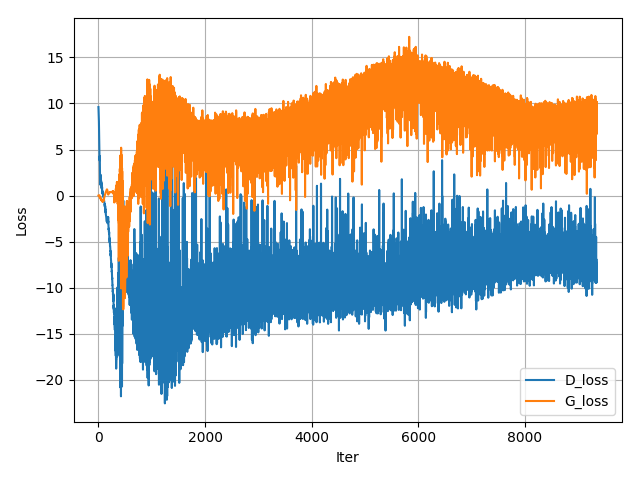
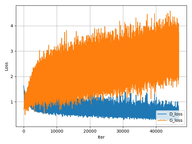
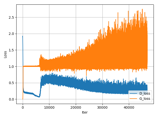
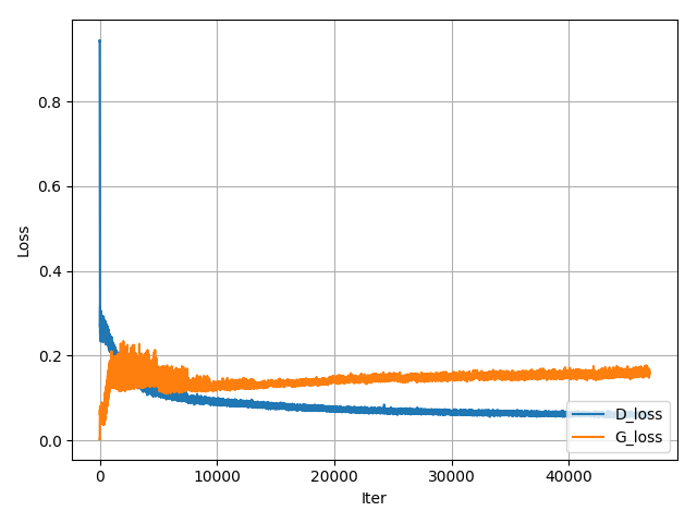
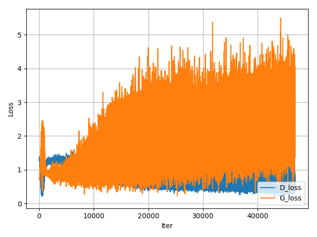
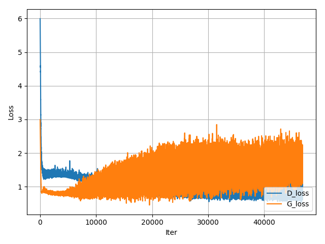
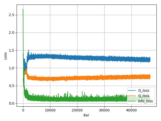
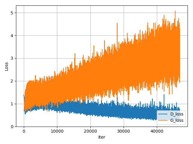
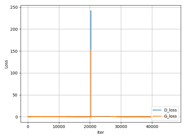
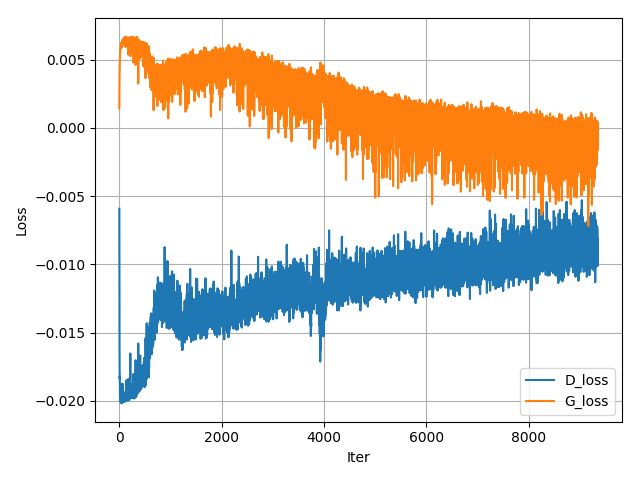
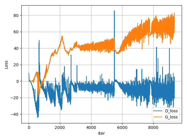
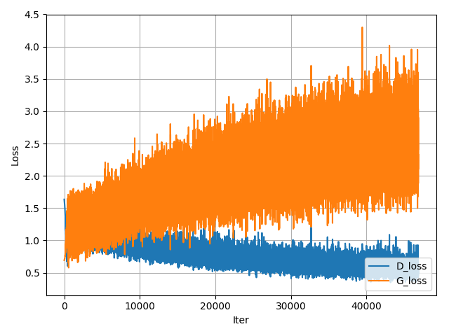
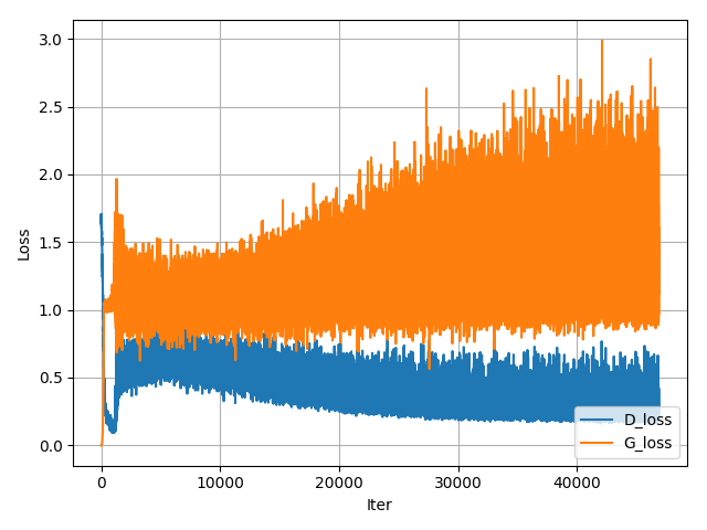
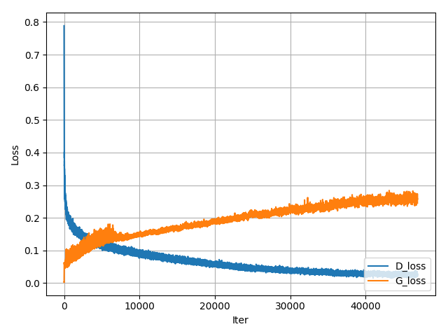
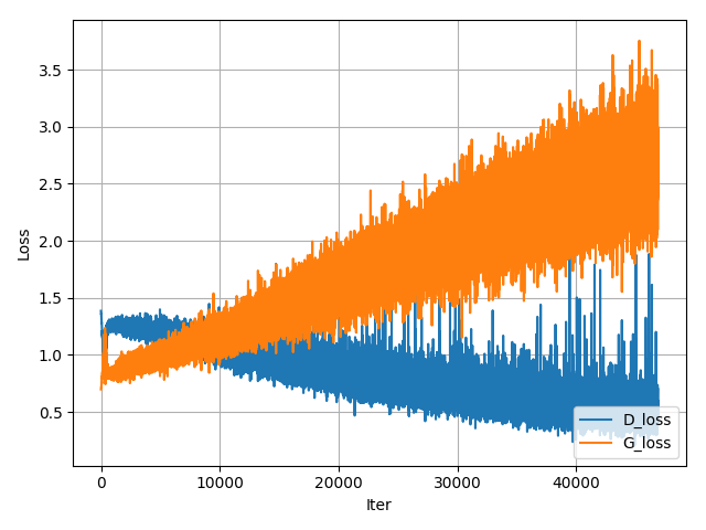
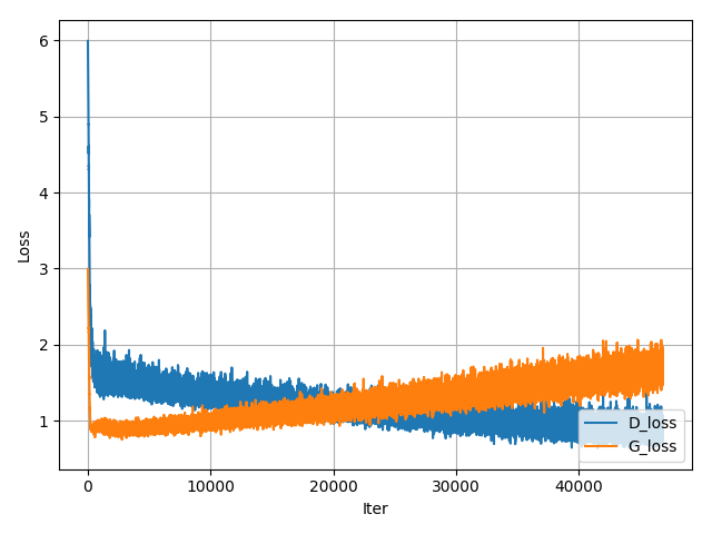
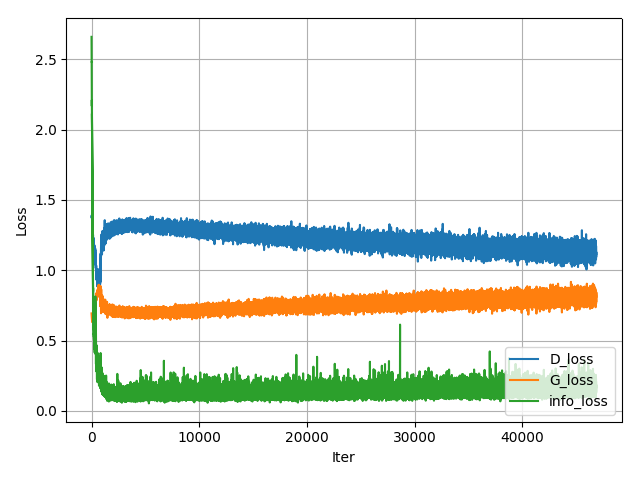
Loss plot
Name
Loss
GAN
LSGAN
WGAN
WGAN_GP
DRAGAN
EBGAN
BEGAN
CGAN
ACGAN
infoGAN
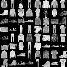
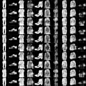
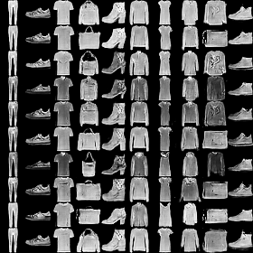
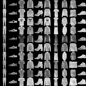
Results for fashion-mnist
Comments on network architecture in mnist are also applied to here. Fashion-mnist is a recently proposed dataset consisting of a training set of 60,000 examples and a test set of 10,000 examples. Each example is a 28×28 grayscale image, associated with a label from 10 classes. (T-shirt/top, Trouser, Pullover, Dress, Coat, Sandal, Shirt, Sneaker, Bag, Ankle boot)
The following results can be reproduced with command:
All results have the same noise vector and label condition, but have different continous vector.
Name
Epoch 1
Epoch 25
Epoch 50
GIF
infoGAN
Loss plot
Name
Loss
GAN
LSGAN
WGAN
WGAN_GP
DRAGAN
EBGAN
BEGAN
CGAN
ACGAN
infoGAN
Folder structure
The following shows basic folder structure.
├── main.py # gateway
├── data
│   ├── mnist # mnist data (not included in this repo)
│   ├── ...
│   ├── ...
│   └── fashion-mnist # fashion-mnist data (not included in this repo)
│
├── GAN.py # vainilla GAN
├── utils.py # utils
├── dataloader.py # dataloader
├── models # model files to be saved here
└── results # generation results to be saved here
Network architecture of generator and discriminator is the exaclty sames as in infoGAN paper.
For fair comparison of core ideas in all gan variants, all implementations for network architecture are kept same except EBGAN and BEGAN. Small modification is made for EBGAN/BEGAN, since those adopt auto-encoder strucutre for discriminator. But I tried to keep the capacity of discirminator.
The following results can be reproduced with command:
All results are generated from the fixed noise vector.
Name
Epoch 1
Epoch 25
Epoch 50
GIF
GAN
LSGAN
WGAN
WGAN_GP
DRAGAN
EBGAN
BEGAN
Conditional generation
Each row has the same noise vector and each column has the same label condition.
Name
Epoch 1
Epoch 25
Epoch 50
GIF
CGAN
ACGAN
infoGAN
InfoGAN : Manipulating two continous codes
All results have the same noise vector and label condition, but have different continous vector.
Name
Epoch 1
Epoch 25
Epoch 50
GIF
infoGAN
Loss plot
Name
Loss
GAN
LSGAN
WGAN
WGAN_GP
DRAGAN
EBGAN
BEGAN
CGAN
ACGAN
infoGAN
Results for fashion-mnist
Comments on network architecture in mnist are also applied to here. Fashion-mnist is a recently proposed dataset consisting of a training set of 60,000 examples and a test set of 10,000 examples. Each example is a 28×28 grayscale image, associated with a label from 10 classes. (T-shirt/top, Trouser, Pullover, Dress, Coat, Sandal, Shirt, Sneaker, Bag, Ankle boot)
The following results can be reproduced with command:
All results have the same noise vector and label condition, but have different continous vector.
Name
Epoch 1
Epoch 25
Epoch 50
GIF
infoGAN
Loss plot
Name
Loss
GAN
LSGAN
WGAN
WGAN_GP
DRAGAN
EBGAN
BEGAN
CGAN
ACGAN
infoGAN
Folder structure
The following shows basic folder structure.
├── main.py # gateway
├── data
│   ├── mnist # mnist data (not included in this repo)
│   ├── ...
│   ├── ...
│   └── fashion-mnist # fashion-mnist data (not included in this repo)
│
├── GAN.py # vainilla GAN
├── utils.py # utils
├── dataloader.py # dataloader
├── models # model files to be saved here
└── results # generation results to be saved here
In order to assist people who are not everyday readers and writer of C++, this library adopts some rules.
All names are in the McciCatena namespace.
In classes with elaborate hierarchy, we normally define a private synonym of Super which refers to the parent class. This is done so that we can change parent/child relationships without breaking code.
We tend to use the m_... prefix on the names of class member fields.
We tend to use this->m_... to refer to class members (rather than omitting this->). We do this for emphasis, and to avoid visual ambiguity.
We tend to name classes starting with a lower-case letter c, i.e., cClassName. For the Catena... classes, we don’t follow this rule, however.
We don’t use most of the standard C++ library (because of the frequent use of exceptions), nor do we use exceptions in our own code. The exception framework tends to be inefficient, and it’s a source of coding problems because the error paths are not directly visible.
However, we do take advantage of some of the C++-11 header files, such as <functional>, <type_traits>, and <cstdint>. (Sometimes we have to do extra work for this.)
Components
Namespace McciCatena
Unless otherwise specified, all symbols are defined inside namespace McciCatena. Usually sketches begin with something like this:
#include<Catena.h>//... other includesusingnamespaceMcciCatena;
Class Catena and header file Catena.h
Catena.h is the main header file for the library. It uses the #defines injected by board.txt and platform.txt from the Arduino environment to create a class named Catena derived from the Catena... class that is specific to the board for which the software is being built. This allows examples to be source-compatible, no matter which Catena is our target.
Board-specific Classes
Catena.h defines the class Catena in terms on one of the following classes based on the setting of the BSP:
MCCI Catena 4610 second-generation Murata-based board with LiPo charging
Catena4611
Catena4611.h
MCCI Catena 4611 second-generation Murata-based board with fixed Vdd, no charging
Catena4612
Catena4612.h
MCCI Catena 4612 second-generation Murata-based board with variable Vdd, no charging.
Catena4617
Catena4617.h
MCCI Catena 4617 second-generation Murata-based board with variable Vdd, no charging
Catena4618
Catena4618.h
MCCI Catena 4618 second-generation Murata-based board with variable Vdd, no charging.
Catena4630
Catena4630.h
MCCI Catena 4630 Murata-based board with Air Quality Sensor.
Catena4801
Catena4801.h
MCCI Catena 4801 Murata-based board with Modbus.
Catena4802
Catena4802.h
MCCI Catena 4802 Murata-based board with Modbus and Temperature sensor.
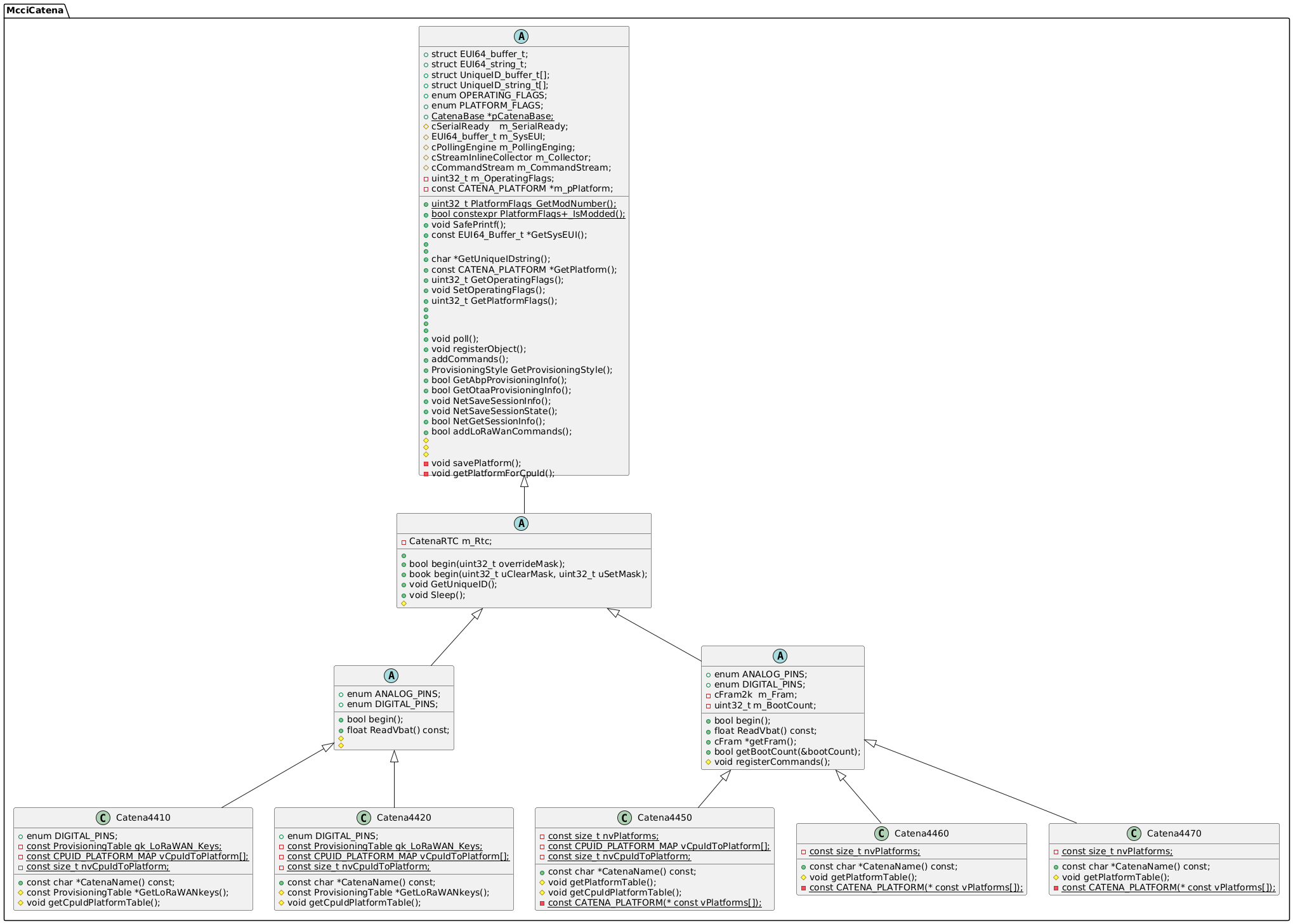
Class derivation
The following figures gives the class derivation hierarchy for the board classes.
The tree is too big to show in one diagram here. So we split according to the two families: STM32-based CPUs, and SAMD-based CPUS.
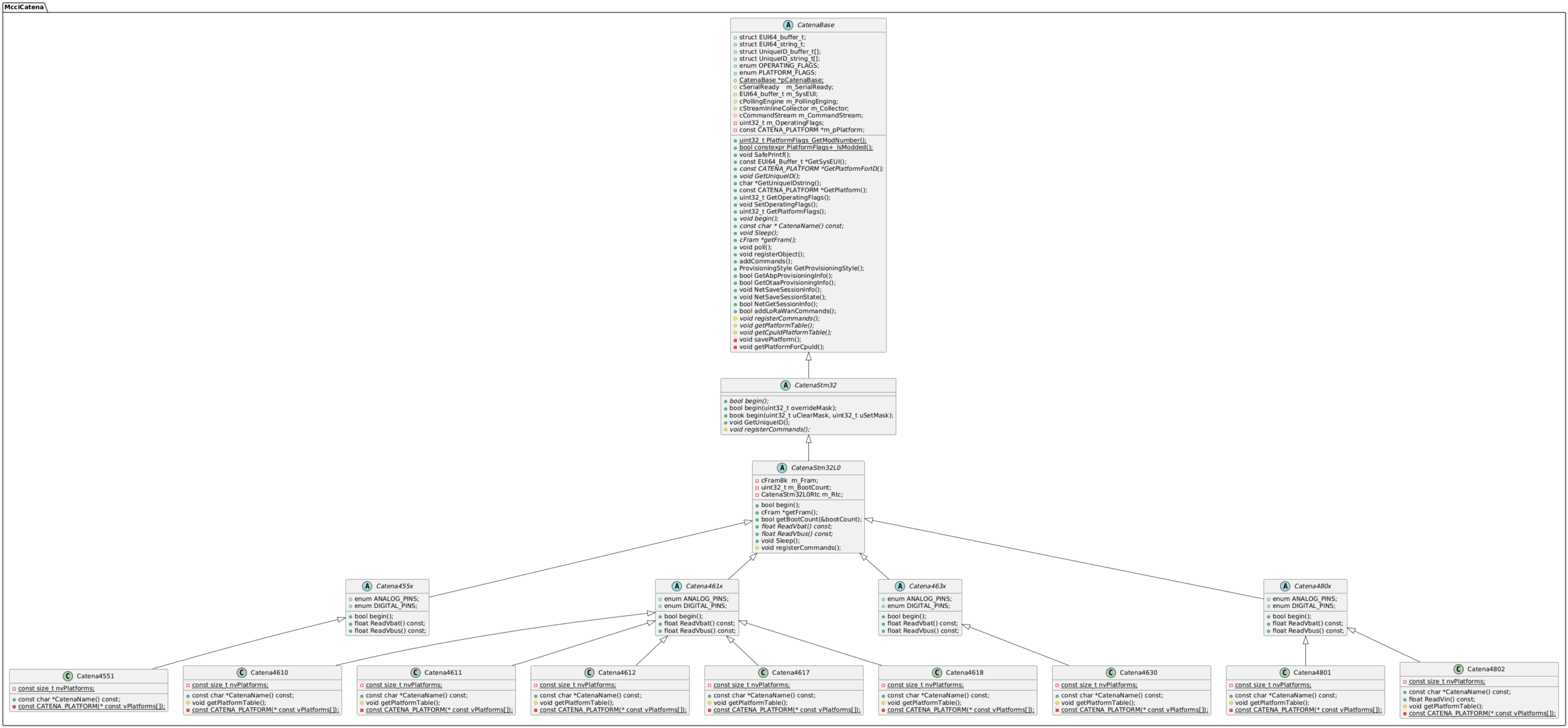
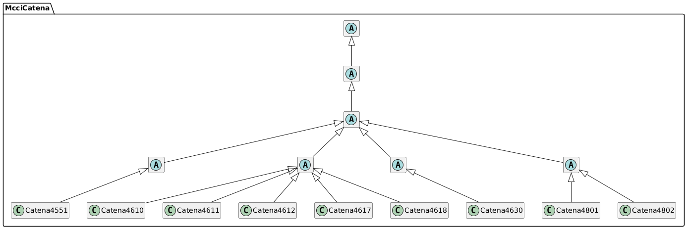
STM32 Classes
The first figure just gives relationships; the second has details about the members of each class.
Catena STM32 Class Relationships:
Catena STM32 Class Hierarchy (full detail):
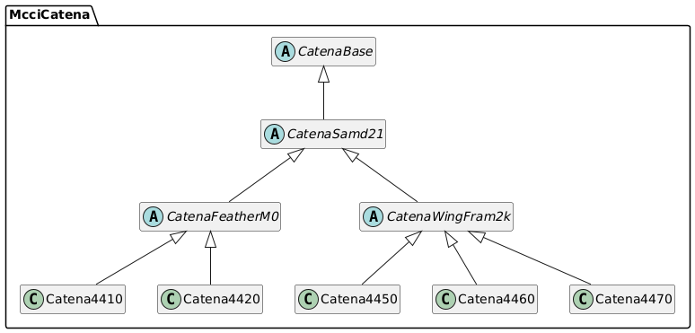
SAMD Classes
The first figure just gives relationships; the second has details about the members of each class.
Catena SAMD Class Relationships:
Catena SAMD Class Hierarchy (full detail):
Platform Management
The hardware supported by this platform is generally similar. The architecture allows for the following kinds of variation (as outlined in the class hierarchy):
CPU differences (Cortex M0, RISC-V, etc.)
SOC differences (SAMD21, STM32L0, etc.)
PC-board differences (different sensors, power supply, capabilities)
Optional component population differences (pull-up resistor values, etc.)
Externally-connected sensors (one-wire temperature sensors, etc.)
Items 1-3 are to some degree known at compile time, based on the Catena model chosen. However, it’s inconvenient to update the BSP for every possible modification, so we allow some variation at run time, guided by the contents of FRAM.
The system is identified to the software by a platform object, of type CATENA_PLATFORM. Several platform objects are built into the firmware image, based on the known variations for component population and external sensors. The appropriate platform object is located at boot time by the Catena Arduino Platform framework. Some values representing possibly variation are stored as PlatformFlags in the CATENA_PLATFORM. This variable is of typePLATFORM_FLAGS.
Platform GUIDs
Each CATENA_PLATFORM has a unique identification. This is a 128-bit binary number called a GUID (or UUID), generated by MCCI during the system design process. The platform GUIDs are defined in the header file Catena_Guids.h. For convenience, here’s a table of the known GUIDs.
All of these names begin with the string GUID_HW_, so we omit that from the tables below.
The M101 and M102 designations are used by the Catena-Sketches family of applications to determine what external sensors are available. This lets them avoid trying to poll external hardware unless the appropriate platform configuration is set. The well known configurations are:
M101: external sensors on screw terminals are contact closures, and should be totalized.
M102: external sensors on screw terminals are a mixture of one-wire temperature sensors and two-wire soil temperature/humidity probes.
The designations “M103” and “M104” are reserved for use by MCCI.
For boards with FRAM, the appropriate platform GUID should be selected and programmed into FRAM using the command system configure platformguid, followed by the GUID value. For boards without FRAM, the library has provisions for tying the GUID to the CPU serial number. Contact MCCI for details.
The tables below were generated from Catena_Guids.h using a script, and then hand annotated. The script is a one-line shell command using awk:
The Catena 4610 uses a LiPo battery like traditional Feathers, and includes a BME280 temperature/pressure/humidity sensor, and a Si1133 light sensor.
Name
GUID
Description
CATENA_4610_BASE
53ca094b-b888-465e-aa0e-e3064ec56d21
Base Catena 4610, assuming no modifications or customizations.
CATENA_4610_M101
6a5d8d0c-d5ae-4143-adc7-8f84ec56a867
Catena 4610 M101, configured for power monitoring and other pulse-input applications.
CATENA_4610_M102
18252b1c-3c0d-403e-8012-224d96c5af06
Catena 4610 M102, configured for environmental monitoring
CATENA_4610_M103
c2cf6cf4-a4c3-4611-941f-6955ffa5bfdc
Catena 4610 M103 — contact MCCI
CATENA_4610_M104
bfed4740-a58a-4ef6-933a-09cb22e93d00
Catena 4610 M104 — contact MCCI
Catena 4611
The 4611 uses a boost regulator that is either on or fully off, controlled by the enable pin. It’s therefore a hybrid between the 4610 (which uses a battery charger switch controlled by the enable pin), and the 4612 (which instead uses the switch to jump from raw Vbat to regulated 3.3V). The 4611 is available by special order from MCCI. Generally, MCCI uses the 4612 instead.
Name
GUID
Description
CATENA_4611_BASE
9bb29dca-0685-4837-8182-3dfa309d279f
Base Catena 4611, assuming no modifications or customizations.
CATENA_4611_M101
4e995471-1570-4767-adae-6657ef871bcd
Catena 4611 M101, configured for power monitoring and other pulse-input applications.
CATENA_4611_M102
964bcf91-9c45-4386-a6e7-5f2d7c3641ef
Catena 4611 M102, configured for environmental monitoring.
CATENA_4611_M103
c85b27cb-7cf9-4025-92bb-2009c08449e5
Catena 4611 M103 — contact MCCI
CATENA_4611_M104
c22be8af-e693-4319-b243-1c2d10197973
Catena 4611 M103 — contact MCCI
Catena 4612
The 4612 runs off an unregulated battery supply, with the option of a boost regulator that can bring the system voltage up to 3.3V.
Name
GUID
Description
CATENA_4612_BASE
915decfa-d156-4d4f-bac5-70e7724726d8
Base Catena 4612, assuming no modifications or customizations.
CATENA_4612_M101
d210a354-c49a-4c4f-856a-4b545dcfaa20
Catena 4612 M101, configured for power monitoring and other pulse-input applications.
CATENA_4612_M102
7fa9709d-17af-463e-ae7f-8210e49acd7a
Catena 4612 M102, configured for environmental monitoring.
CATENA_4612_M103
ff8b2ac6-75cd-4ed3-980b-50b209e64551
Catena 4612 M103 — contact MCCI
CATENA_4612_M104
dea48489-cdac-43f4-b8ad-edb08ce21546
Catena 4612 M103 — contact MCCI
Catena 4617
The Catena 4617 is a variant of the Catena 4612 with a IDT HS3001 temperature/humidity sensor in place of the Bosch BME280.
Name
GUID
Description
CATENA_4617_BASE
6767c2f6-d5d5-43f4-81af-db0d4d08815a
Base Catena 4617, assuming no modifications or customizations.
Catena 4618
The Catena 4618 is a variant of the Catena 4612 with a Sensirion SHT31-DIS-F temperature/humidity sensor in place of the Bosch BME280.
Name
GUID
Description
CATENA_4618_BASE
b75ed77b-b06e-4b26-a968-9c15f222dfb2
Base Catena 4618, assuming no modifications or customizations.
Catena 4630
The Catena 4630 is a variant of the Catena 4610. It deletes the Si1131 light sensor, and adds an IDT ZMOD4410 atmospheric gas sensor, plus a connection for an external Plantower PMS7003 PM2.5/dust sensor.
Name
GUID
Description
CATENA_4630_BASE
17281c12-d78a-4e4f-9c42-c8bbc5499c91
Base Catena 4618, assuming no modifications or customizations.
GUIDs for the Catena 4450/4460/4470 family
Catena 4450
The 4450 Feather Wing includes a BME280 temperature/humidity/pressure sensor, and a BH1750 lux sensor.
Name
GUID
Description
CATENA_4450_BASE
60480acb-dc5d-4148-b6c9-aca13449cf1d
Base Catena 4450, assuming no modifications or customizations.
CATENA_4450_M101
82bf2661-70cb-45ae-b620-caf695478bc1
Catena 4450 M101, configured for power monitoring and other pulse-input applications.
CATENA_4450_M102
2281255e-ac5c-48cb-a263-9dc890d16638
Catena 4450 M102, configured for environmental monitoring.
CATENA_4450_M103
1fb2506f-0f2a-4310-9e6a-9bc191e0ae12
Catena 4450 M103 — contact MCCI
CATENA_4450_M104
a731f637-e3ed-4088-a9a8-f54b6671dcf6
Catena 4450 M103 — contact MCCI
Catena 4460
The 4460 Feather Wing includes a BME680 air quality sensor, and a BH1750 lux sensor.
Name
GUID
Description
CATENA_4460_BASE
3037d9be-8ebe-4ae7-970e-91915a2484f8
Base Catena 4460, assuming no modifications or customizations.
CATENA_4460_M101
31e563d1-0267-43fc-bca0-9a4cb5bfc55a
Catena 4460 M101, configured for power monitoring and other pulse-input applications.
CATENA_4460_M102
494f3c17-8ac1-4f80-8ecc-ca4dd3dccbdc
Catena 4460 M102, configured for environmental monitoring.
CATENA_4460_M103
a882186f-f4ab-4ee4-9402-7b628a76d886
Catena 4460 M103 — contact MCCI
CATENA_4460_M104
398a9e5a-e22f-4265-9d35-bf45433ddbe3
Catena 4460 M103 — contact MCCI
Catena 4470
The 4470 Feather Wing includes a BME280 temperature/humidity/pressure sensor, a BH1750 lux sensor, and a Modbus/RS-485 interface connected to Serial1.
Name
GUID
Description
CATENA_4470_BASE
ea8568ec-5dae-46ee-929a-a3f6b00a565e
Base Catena 4470, assuming no modifications or customizations.
CATENA_4470_M101
dd0a37a6-e469-43ec-b173-fed795129455
Catena 4470 M101, configured for power monitoring and other pulse-input applications.
GUIDs for the Catena 480x family
Catena 4801
Name
GUID
Description
CATENA_4801_BASE
10ea7e25-a4a4-45fd-8959-c04a6a5d7f95
Base Catena 4801, assuming no modifications or customizations.
Catena 4802
Name
GUID
Description
CATENA_4802_BASE
daaf345e-b5d5-4a32-a303-3ac70b81d260
Base Catena 4802, assuming no modifications or customizations.
GUIDs for Adafruit Feather M0s
MCCI also uses this library with Feather M0s without MCCI hardware. These GUIDs are useful in that situation.
Name
GUID
Description
FEATHER_M0_LORA_TTNNYC
a67ad93c-551a-47d2-9adb-e249b4cf915a
Feather M0 LoRa, modified per The Things Network NYC standards — DIO1 connected to D6.
FEATHER_M0_LORA
e2deccc8-55fa-4bd3-94c3-ce66bcd0baac
Feather M0 LoRa, but DIO1 connection is not known.
FEATHER_M0_PROTO_WINGLORA_TTNMCCI
3bab150f-6e32-4459-a2b6-72aced75059f
Feather M0 Proto with a separate LoRa Feather Wing. This is sometimes known as an MCCI Catena 4420.
FEATHER_M0_PROTO
f6a15678-c7f3-43f4-ac57-67ef5cf75541
A Feather M0 Proto.
FEATHER_M0
2e6dfed4-f577-47d5-9137-b3e63976ae92
Some unspecified member of the Feather M0 family.
Polling Framework
When composing software from components, it’s inconvenient and bug-prone to have to manually edit the Arduino loop() function to poll each component.
To compensate, the Catena platform defines a framework for polling, and allows components to register to be polled.
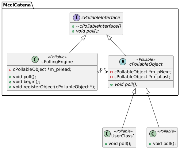
The foundation of the framework is cPollableInterface, an abstract class. Any object inheriting from cPollableInterface will provide a poll() method; this provides a standard way to poll an object.
Pollable objects are managed via a central instance of cPollingEngine, which works on objects that are derived from cPollableObject. You create your pollable class by arranging for it to inherit from cPollableObject; then at run time you arrange to register and normally created by arranging for them to inherit from cPollableObject. This adds a few tracking fields to your class, and makes them available to the cPollingEngine when you register the object with the polling engine.
The abstract relationships are shown below.
Making a class pollable
Let’s say that UserClass1 exists and has the following definition.
To make UserClass1 pollable, you change the class declaration as follows:
Change UserClass1 to inherit from McciCatena::cPollableObject, using multiple inheritance if needed. List McciCatena::cPollableObject last. No need to make it public.
Declare a new public virtual method void poll(). We recommend that you use the override keyword to make it clear that this is an override for a method declared in the parent class.
You also, of course, must supply an implementation of UserClass::poll().
Each instance of your pollable class (in our example, each instance of type UserClass1) must be registered with a polling engine. The most convenient polling engine to use is the once provided by the CatenaBase class, which is normally instantiated as gCatena. Simply call gCatena.registerObject() to register your object with the Catena polling engine. So for example:
#include<Catena.h>// create the gCatena instance.
McciCatena::Catena gCatena;
// create an instance of my object.
UserClass1 myUserObject;
voidsetup() {
// conventionally, we call gCatena.begin() first:gCatena.begin();
// now register the object.gCatena.registerObject(&myUserObject);
}
voidloop() {
// poll all the objects registered with gCatena.gCatena.poll();
// do any other work...
}
If you’re not using the full Catena class framework, you still can use polling; just declare your own cPollingEngine instance. For example:
#include<Arduino.h>
#include<Catena_PollableInterface.h>// create the polling engine instance.
McciCatena::cPollingEngine gPollingEngine;
// create an instance of my object.
UserClass1 myUserObject;
voidsetup() {
// conventionally, we call gPollingEngine.begin() first:gPollingEngine.begin();
// now register the object.gPollingEngine.registerObject(&myUserObject);
}
voidloop() {
// poll all the objects registered with gCatena.gPollingEngine.poll();
// do any other work...
}
Finite State Machine (FSM) Framework
Finite state machines are very useful when implementing non-blocking asynchronous programs, or modeling external hardware that changes state independently of the system.
We’ve ported an implementation of MCCI’s standard FSM approach. It’s good for Mealy or Moore designs, and is intended to be easy to implement and maintain. This version is C++ oriented; it assumes that each FSM instance is associated with a C++ class object (the “parent” object). The work of implementing the FSM is divided between the parent object and the FSM object. The FSM object does all the bookkeeping and handling of corner conditions; the parent object provides a method function, which the FSM calls whenever it seems appropriate to do so.
Here’s what you need:
an enum class type with all of your states, and a couple of distinguished states. This type is referred to as TState; and
an associated C++ class type (referred to as TParent), containing…
a method that will be used as the dispatcher by the evaluator, of signature TParent::someName(TState currentState, bool fEntry) -> TState.
In addition to the states relevant to your problem, TState must have three distinct values with well-known names.
TState::stNoChange does not correspond to any state. Instead, it’s the value returned by the dispatch routine when the state is not to be changed. (Returning the current state will cause the FSM to transition from the current state to the current state.)
TState::stInitial is the initial state of your FSM.
TState::stFinal is the final state of your FSM. Once the FSM reaches this state, it will remain there until another call to fsm.init() is made.
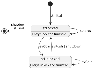
The author usually starts by drawing a diagram, labeled with the states and transitions.
For example, here’s the turnstile state diagram:
Defining the state enum class
Define an enum class as follows:
enumclassMyStateEnum {
stNoChange = 0, // this name must be present: indicates "no change of state"
stInitial, // this name must be presnt: it's the starting state.// use-case-specific states// ...
stFinal, // this name must be present, it's the terminal state.
};
For example, for the turnstile diagram:
enumclassState {
stNoChange = 0, // this name must be present: indicates "no change of state"
stInitial, // this name must be presnt: it's the starting state.
stLocked,
stUnlocked,
stFinal, // this name must be present, it's the terminal state.
};
Identify the parent class
This means finding the class name for the class that is going to contain this FSM. One class can contain many FSMs, but each FSM class has only one parent class.
For our example, we’ll say that the class modeling turnstiles is Turnstile.
Add the state type to the parent class
Add the type you defined above to the parent class. For example:
classTurnstile {
// states for FSMenumclassState {
stNoChange = 0, // this name must be present: indicates "no change of state"
stInitial, // this name must be presnt: it's the starting state.
stLocked,
stUnlocked,
stFinal, // this name must be present, it's the terminal state.
};
};
Define the FSM instance in the parent class
Add an FSM instance as a member of the parent class. It’s up to you whether to make it public, private, or protected.
classTurnstile {
// states for FSMenumclassState {
stNoChange = 0, // this name must be present: indicates "no change of state"
stInitial, // this name must be presnt: it's the starting state.
stLocked,
stUnlocked,
stFinal, // this name must be present, it's the terminal state.
};
// the FSM instance
McciCatena::cFSM<Turnstile, State> m_fsm;
};
Declare a method function in the parent class
Finally, we have to declare a method function that the FSM can call. Extending the turnstile example again:
classTurnstile {
// states for FSMenumclassState {
stNoChange = 0, // this name must be present: indicates "no change of state"
stInitial, // this name must be presnt: it's the starting state.
stLocked,
stUnlocked,
stFinal, // this name must be present, it's the terminal state.
};
// the FSM instance
McciCatena::cFSM<Turnstile, State> m_fsm;
// the FSM dispatch function called by this->m_fsm.
State fsmDispatch(State currentState, boolfEntry);
};
Implement the FSM dispatch function
Your FSM dispatch function will look like this.
voidTurnstile::fsmDispatch(Turnstile::State currentState, boolfEntry) {
State newState = State::stNoChange;
switch (currentState) {
case State::stInitial:
if (fEntry) {
// entry is not considered in this state, always move on.
}
digitalWrite(LOCK, 1);
pinMode(LOCK, OUTPUT);
newState = State::stLocked;
break;
case State::stLocked:
if (fEntry) {
digitalWrite(LOCK, 1);
}
if (this->m_evShutdown) {
this->m_evShutdown = false;
newState = State::stFinal;
} elseif (this->m_evCoin) {
this->m_evCoin = false;
newState = State::stUnlocked;
} elseif (this->m_evPush) {
this->m_evPush = false;
// stay in this state.
} else {
// stay in this state.
}
break;
case State::stUnlocked:
if (fEntry) {
digitalWrite(LOCK, 0);
}
if (this->m_evShutdown) {
this->m_evShutdown = false;
newState = State::stFinal;
} elseif (this->m_evCoin) {
this->m_evCoin = false;
// stay in this state.
} elseif (this->m_evPush) {
this->m_evPush = false;
newState = State::stLocked;
} else {
// stay in this state.
}
break;
case State::stFinal:
// by policy, we idle with the turnstile locked.digitalWrite(LOCK, 1);
// stay in this state.break;
default:
// the default means unknown state.// transition to locket.
newState = State::stLocked;
break;
}
return newState;
}
Implement the FSM initialization
Somewhere in your initialization for Turnstile, add the following code. For example, if Turnstile has a Turnstile::begin() method, you could write:
voidTurnstile::begin() {
// other init code...// set up FSMthis->m_fsm.init(*this, fsmDispatch);
// remaining init code...
}
The general time/date class McciCatena::cDate
When logging data, we frequently need to keep time on a scale that is correlated with other devices. Although the Arduino environment provides interval times based on the seconds(), millis() and micros() APIs, there’s no built-in concept of calendar time. The cDate class provides calendar time objects and the ability to perform conversions between calendar time and interval time. The cDate object is also an important component for clock drivers.
#include<Catena_Date.h>// allocate a date object, initially invalid
McciCatena::cDate myDate;
Interval Seconds
It’s common to compare intervals and transmit timestamps using a simple up-counter. Traditional Posix systems count seconds since 1970-01-01 00:00:00Z; GPS systems count seconds since 1980-01-06 00:00:00Z. These base times are commonly called “epochs”. Times can be (theoretically) in the past (negative) or future (positive) relative to the epoch. For a variety of reasons, we call times based on the Posix epoch “Common times”; we call times based on the GPS epoch “GPS times”. The types CommonTime_t and GpsTime_t are used to record times in common and GPS times. Both are of type std::int64_t. Both have a range of designated values that are valid; this range is chosen to allow any valid CommonTime_t to be converted to GpsTime_t and vice versa.
Many numerical values of std::int64_t are not valid times. The library uses kCommonInvalidTime and kGpsInvalidTime when it needs to create an invalid time, but it (and clients of the library) should use isCommonTimeValid() or isGpsTimeValid() to check whether a given time is in fact valid.
getCommonTime() and getGpsTime() convert valid times between the two systems, handling invalid cases.
cDate calendar types
The types cDate::Year_t, cDate::Month_t, cDate::Day_t, cDate::Hour_t, cDate::Minute_t, cDate::Second_t are used to represent years (from 0 to 65535), months (from 1 to 12), days (from 1 to 28, 29, 30, or 31, depending on the month and year), hours (0 to 23), minutes (0 to 59), and seconds (0 to 59). The year zero corresponds to ISO-8601 year zero. We use, technically speaking, a proleptic Gregorian calendar with astronomical year numbering (i.e., year zero).
cDate properties
boolcDate::isValid() const;
This function returns true if the entries in the cDate object are valid, false otherwise.
These functions return the CommonTime_t or GpsTime_t equivalent of the date object.
cDate methods
boolcDate::setDate(Year_t y, Month_t m, Day_t d);
Set the date portion of the cDate instance (only if a valid date is passed). Return true if and only if the date was updated.
boolcDate::setTime(Hour_t h, Minute_t m, Second_t s);
Set the time portion of the cDate instance (only if a valid time is passed). Return true if and only if the time was updated. Time is set in zone UTC+0.
Set the date and time of the cDate instance from the common or GPS time stamp. Returns false if the incoming timestamp is invalid, or if the specified time is out of range.
Timekeeping, solar days, leap seconds
This section is provided for background, and can be skipped if you’re not interested in the theory behind the implementation.
Timekeeping is a thorny topic for scientific investigations, because one day is not exactly 86,400 seconds long. Obviously, the difference between two instants, measured in seconds, is independent of calendar system, but converting the time of each instant into ISO date and time is not independent of the calendar. Worse is that computing systems (e.g. POSIX-based systems) focus more on easy, deterministic conversion from a time serial number to UTC time, and so assume that there are exactly 86400 seconds/day. In UTC time, the solar calendar date is paramount; leap-seconds are inserted or deleted as needed to keep UTC mean solar noon aligned with astronomical mean solar noon.
In effect, the computer observes a sequence of seconds. We need to correlate them to calendar time, and we need to interpret know the interval between instances. Let’s call the sequence of seconds interval time, as opposed to calendar time.
Let’s also define an important property of sequences of seconds — “interval-preserving” sequences are those in which, if T1 and T2 are interval second numbers, (T2 – T1) is equal to the number of ITU seconds between the times T1 and T2.
Real-time calendar clocks typically measure intervals using a mixed-radix system (year/month/day hour:minute:second). This looks much like UTC calendar time, but in fact doesn’t include leap seconds, and is a pure interval counter (with inconvenient arithmetic).
There are (at least) three ways of relating interval time to calendar time.
Keep interval time interval-preserving, and convert to calendar time as if days were exactly 86,400 seconds long. (GPS is such a time scale.) Differences between instants (in seconds) are in ITU seconds.
Keep interval time interval-preserving, but convert to calendar time accounting for leap seconds (most days are 86,400 seconds long, but some days are 86,399 seconds long, others are 86,401 seconds long). (UTC is such a time scale.) Differences between instants (in seconds) are in ITU seconds.
Make interval time not interval-preserving by considering leap seconds. A day with 86,401 ITU seconds will have two seconds numbered 86,399; a day with 86,399 ITU seconds will not have a second numbered 86,399. Convert to date/time as if days were exactly 86,400 seconds long. The difference between two instants (in interval time) is not guaranteed to be accurate in ITU seconds. This is how POSIX time works.
Steve Allen’s website has a number of good discussions, including:
The onboard real-time clocks provided by various Catena platforms count intervals in “calendar” time, and are set by people (again in “calendar” time) from watches etc. that run from UTC or a derivative. We avoid the additional complication of local time zones by assuming that the user will use GMT (UTC+0, or “Zulu” time) We will assume that the user can input the time in Zulu time and that the battery-backed RTC is recording time in Zulu time.
Therefore, we use a timescale that simply states that days have 86,400 seconds. In effect, we choose option 1 above. In our applications, we think that this will be good enough. If we ever start to use LoRaWAN (“GPS”) time, we assume that the network will be able to send us the information needed to convert to calendar time as needed. This may add a little complication but it’s future complication and we’ll deal with all this if the need arises.
LoRaWAN Support
The Catena Arduino Platform includes C++ wrappers for LoRaWAN support, based on the MCCI version of the Arduino LMIC library and MCCI’s Arduino LoRaWAN library. It includes command processing from the Serial console for run-time (not compile-time) provisioning, and uses the non-volatile storage provided by the Catena FRAM to store connection parameters and uplink/downlink counts.
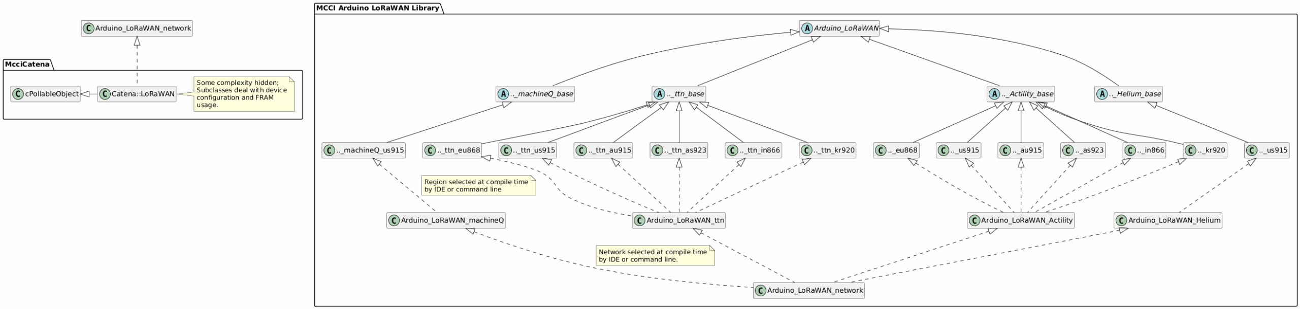
The Catena::LoRaWAN class is derived from the Arduino_LoRaWAN class defined by <Arduino_LoRaWAN.h>.
Instantiate the global Catena object, with the name gCatena.
#include<Catena.h>usingnamespaceMcciCatena;// to save typing
Catena gCatena; // instantiate the Catena platform object.
Instantiate the global LoRaWAN object, with the name gLoRaWAN:
Catena::LoRaWAN gLoRaWAN; // the LoRaWAN function.
In your setup function, initialize gCatena, gLoRaWAN, and register gLoRaWAN as a pollable object (see Polling Framework).
voidsetup() {
// other things// set up Catena platform.gCatena.begin();
// set up LoRaWANgLoRaWAN.begin(&gCatena);
gCatena.registerObject(&gLoRaWAN);
// other things
}
Sending an uplink message
Use the Catena::LoRaWAN::SendBuffer() method to send an uplink message. Usually it’s best to send it with an asynchronous callback, so that’s what we’ll show.
SendBuffer attempts to start the transmission of a buffer. This attempt might fail for several reasons, for example:
A transmission might already be in progress.
The LoRaWAN system might not be properly provisioned with device identity and suitable keys.
The LoRaWAN system might be shut down.
If the transmission is not accepted, SendBuffer() returns false.
If the transmission is accepted, then the following steps are taken:
pDoneFn and pClientData are saved internally for use when the transmission completes.
The data from pUplinkBuffer is copied into an internal buffer (so you can immediately start reusing the buffer in your own code).
If the device is provisioned for OTAA mode, and the device is not yet joined to a network, a JOIN attempt is initiated; and the message is transmitted if the JOIN attempt succeeds.
The message is transmitted on the uplink port specified by port. If fConfirmed is true, a confirmed (acknowledged) uplink is used; otherwise unconfirmed uplinks are used.
Control then returns to the caller (with the result true).
When the transmission attempt finishes, the LoRaWAN subsystem calls pDoneFn(pClientData, fSuccess), with fSuccess true if the uplink seemed to be successful. Success means different things in different circumstances.
For an unconfirmed uplink, success means that the device is joined to a network, and was able to transmit the message without any local errors. If not joined, and the join attempt fails, then fSuccess will be false.
For a confirmed uplink, success means that the message was sent, and a confirmation downlink was received. Failure doesn’t necessarily mean that the network didn’t receive the message; it only means that we didn’t get an acknowledgement.
Registering to receive downlink messages
Receiving a message is a somewhat passive operation. The client registers a callback with gLoRaWAN; later, whenever a downlink message is received, the client’s callback is called.
In order to allow code to be portable across networks and regions, we’ve done a lot of work with abstraction classes. If you’re curious, here’s a somewhat simplified diagram (click on the diagram to get an enlarged SVG version).
As the diagram shows, Catena::LoRaWAN objects are primarily Arduino_LoRaWAN derivatives, but they also can be viewed as McciCatena::cPollableObject instances, and therefore can participate in polling.
FRAM Storage Management
Many MCCI Catena models include FRAM storage for keeping data across power cycles without worrying about the limited write-tolerance of EEPROM or flash. (FRAM, or ferro-electric RAM, is essentially non-volatile memory that can be freely written. Flash EPROM and EEPROM can be written, but tend to have non-local error properties and limited write durability. They are good for storing code, but troublesome for storing counters, because a location must be updated each time a counter is written.)
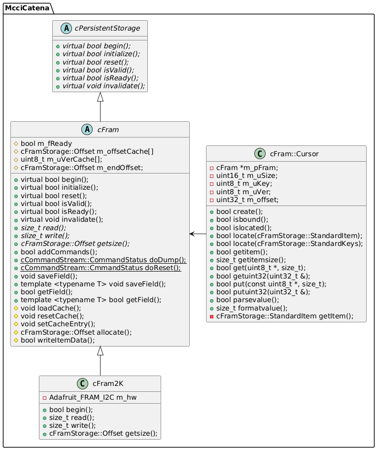
The abstract class cFram is used to represent a FRAM-based storage element. It is abstract in that is uses several virtual methods that must be supplied by the concrete class that represents the specific FRAM chip. (For example, cFram2K represents a 2k by 8 FRAM.)
FRAM Storage Formats
All FRAMs managed by cFram use a common object format on the FRAM, defined by the header file Catena_FramStorage.h.
Storage is viewed as a linear sequence of objects.
Each object uses a common format.
Each object consists of a common 24-byte header followed by a variable-length storage field.
Objects are always a multiple of 4 bytes long.
Objects are identified by “globally unique ID” (or GUID) and “key” (an 8-bit value). GUIDs are 16-byte values, generated by a standard algorithm with low likelihood of collision. We considered using one GUID for each object, but that would consume a lot of room in system flash memory. So instead, we use an extra one-byte key, which allows most objects to share a common GUID. This approach allows for more space-efficient code on systems with limited system memory.
Each standard object contains a data payload. For any given object, the payload size is fixed when the object is created.
Objects normally contain two payload slots. The slots are written alternately (so that the old version is always available). A voting scheme is used to determine which slot is currently live. Three bytes are used for storing the “current” slot indicator, and are updated only after the new data have been written. A system interruption before the second byte of the trio is written will cause the system to use the old value after recovering from the problem; a system interruption after the second byte of the trio is written will cause the system to use the new value.
The first uint32_t of an object records the overall size of the object, and the size of each data payload slot. Objects are always required to be a multiple of 4 bytes long, so the size is recorded as a count of uint32_t values. Objects are allowed to be up to 2^18 bytes long. Data payload fields are specified in bytes, and are limited to [0..32767] bytes.
There is an escape clause. If bit 31 of the first uint32_tis set, the object is not “standard”. In such a case, the contents of the object after the standard header cannot be used for a standard data payload (as defined above). This may be desirable payloads that are written only once, when the FRAM is initialized; but it leaves redundancy management to the client.
This format is summarized in the following tables.
Object Storage Structure
Bytes
Name
Type
Description
0..3
uSizeKey
uint32_t
The size of the overall object, and the size of a datum within the object. This item is stored in little-endian format. The bit layout is shown below.
4..19
Guid
MCCIADK_GUID_WIRE
the 16-byte globally-unique ID of the object. This GUID is stored in wire order (big endian).
20
Key
uint8_t
An additional byte of name, allowing up to 256 objects to be defined by a single common GUID.
21..23
uVer[3]
uint8_t[3]
Array of current slot indicators. Normally these are all identical and either 0x00 or 0x01. However, after a system upset, it is possible that these will not be the same. If uVer[0] is equal to uVer[1], then the slot is selected by the value of these bytes. Otherwise, the slot is selected by the value of uVer[3].
24..size-1
–
–
Reserved space for the data payload. Slot zero starts at byte 24 and runs for the number of data bytes defined by bits 30..16 of uSizeKey. Slot one starts immediately after slot zero.
Bit layout of uSizeKey
Bits
Name
Mask
Description
15..0
Size
cFramStorage::SIZE_MASK
The size of the object in “clicks”. Each click is four bytes.
30..16
DataSize
cFramStorage::DATASIZE_MASK
The size of the object’s data payload in bytes. This may be zero.
31
fNonStandard
cFramStorage::NONSTD_MASK
If zero, the object’s payload uses the redundant scheme described above; the payload size is necessarily limited to 32767 byes. If non-zero, the object’s payload uses a client-supplied encoding and representation; but can use up to 256 k bytes (since the object size can represent up to 256 k bytes)
The FRAM header object
An FRAM store managed by this library is expected to begin with a header object. A header object is identified by the well-known GUID {1DE7CDCD-0647-4B3C-A18D-8138A3D9613F} and the key kHeader (zero).
The header object carries a single 4-byte (uint32_t) payload, which is interpreted as the end-of-storage address — the offset of the first byte on the FRAM that is not used for object storage. If an object is added to the store, this pointer is updated after the new object object has been fully committed. The new object is not permanently committed until the end-of-storage pointer is atomically updated.
Adding FRAM objects
Determine the GUID and key you want to use. If you are adding the item as part of the Catena library, you can use the GUID GUID_FRAM_CATENA_V1(WIRE), {1DE7CDCD-0647-4B3C-A18D-8138A3D9613F}; add the key to McciCatena::cFramStorage::StandardKeys, defined in Catena_FramStorage.h.
There is no presentable way to use a non-standard GUID; several changes must be made in Catena_Fram.cpp to enable this.
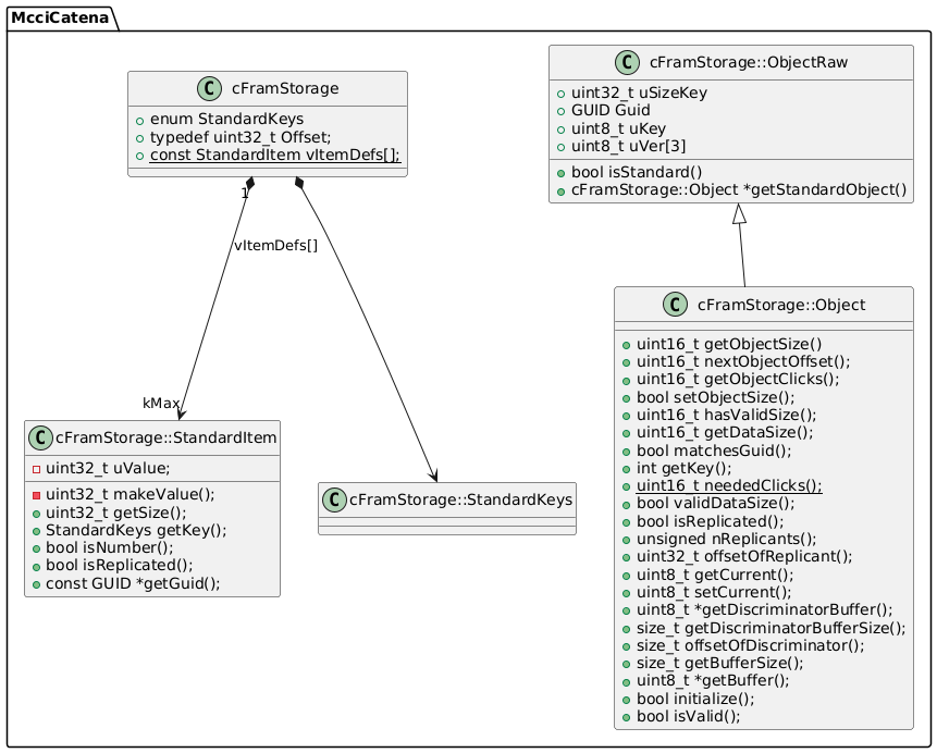
Ultimately, the metadata for your new object is represented by a 32-bit value of type cFramStorage::StandardItem. The constructor takes three (optionally four) arguments:
uKey, the 8-bit key value
uSize, the 16-bit object size. (If your object is variable size, you must specify a maximum size, and the actual size of the object must be represented as part of the object data somehow.)
fNumber, a Boolean value. If true, then the value represents a little-endian value; if false, big-endian. This is used for displays and the command interpreter.
Optionally fReplicated (assumed true), which controls whether the replicated data-storage scheme should be used.
Find the table McciCatena::cFramStorage::vItemDefs[] in Catena_FramStorage.cpp, and add your StandardItem value at the appropriate offset.
To query the value of your object, you can use gCatena.getFram()->getField(uKey, Value); this is a templated function which will set Value according toe the current value stored for uKey.
You may also use gCatena.getFram()->getField(uKey, (uint8_t *)&buffer, sizeof(buffer)).
To set the value of your object, you can use gCatena.getFram()->saveField(uKey, Value); this is a templated function which will write Value to the object identified by uKey.
You may also use gCatena.getFram()->saveField(uKey, (const uint8_t *)&buffer, sizeof(buffer)).
Class hierarchy within the FRAM library
Asynchronous Serial Port Command Processing
The Catena Arduino platform provides both an asynchronous command-line collection object and a full command parser.
The Catena::begin() method normally creates a command parser instance that’s linked to a command parser instance. For
Collecting lines asynchronously from streams
The header file Catena_StreamLineCollector.h defines the class cStreamLineCollector. This class is a cPollableObject, and as such is polled automatically by the governing cPollingEngine. A read is launched by calling cStreamLineCollector::readAsync(), passing a callback function, a buffer (base and size), and a context handle. When a command has been accumulated, the specified callback function is called according to the following prototype:
pCtx is the user-supplied context parameter passed to cStreamLineCollector::readAsync.
uStatus indicates whether the read was successful, and gives a rough idea of the failure reason if not.
pBuffer points to the first byte of data. This might be nullptr in case of error, and it might be different than the user’s original buffer pointer.
nBuffer is passed as the actual number of data bytes in the buffer. In case of error, nBuffer will be zero.
The command parser
A command parser is initialized with a reference to a cStreamLineCollector instance and a convenience reference to the governing cCatena instance. It is initialized with
The command parser works by parsing the input line into words, and then finding the command in command tables, which the client registers at run time using the following function:
Multiple command tables can be registered dynamically; this allows modules to add commands as they are initialized. There’s no need to edit a central command table.
The command tables consist of a top-level cCommandParser::cDispatch instance. This is not a const — it has bookkeeping entries to help with building the tables at runtime without requiring malloc(). The dispatch instance points in turn to a
In the first case, the commands are each entered into the top-level name space. In the second case, a top-level command named groupname is entered, and each of the commands in the table is entered as a secondary command.
The command tables themselves are simple arrays of name/function pointer pairs.
pThis points to the parent cCommandStream instance. pContext is the user data from the relevant cCommandStream::cDispatch object. argc and argv are very much like the command arguments to a C main() function. argv[0] is the matching command, and argv[1..argc-1] are the parsed arguments from the command line.
A command function may operate synchronously or asynchronously.
Command stream methods for use by functions
Command stream functions may call any of these functions:
pThis->printf() formats results to pass back to the command source.
pThis->getuint32() scans an argument and converts to uint32_t.
pThis->completeCommand(CommandStatus) signals the completion of an asynchronous command.
Synchronous Command Functions
A synchronous command function does all of its work in the initial function call, and returns a status code. The status code can be any value exceptCommandStatus::kPending. Synchronous commands must not call pThis->completeCommand(CommandStatus).
Asynchronous Command Functions
An asynchronous command function allows for work to continue after the initial function call. The main command function typically has two parts.
The first part of the command is normally coded synchronously; it checks parameters, etc., and returns non-kPending status. In this part of the command, there’s no chance of pThis->completeCommand being called.
The second part of the command is coded asynchronously. The asynchronous paths each call pThis->completeCommand() when all work has been done. Once the function has established at least one asynchronous completion path, the main function must return kPending (and must ensure that all the completion paths call completeCommand()).
Clock Management and Calibration
On some platforms, the system clock needs to be calibrated explicitly in order for the real-time ticks from micros() and millis() to be accurate. Do this by calling uint32_t gCatena.CalibrateSystemClock(). This function updates the clock calibration, and returns a platform-specific value indicative of the calibration. On platforms that don’t support (or that don’t need) calibration, a dummy implementation is provided that returns 0.
Watchdog Timer
The independent watchdog is used to detect and resolve malfunctions due to software failures. It triggers a reset sequence when it is not refreshed within the expected time-window (we use 26 seconds time-window). Along with the watchdog timer, we use SafeDelay() function.
SafeDelay()
It serves as an alternative to the Arduino delay() function. Its purpose is to refresh the watchdog time-window, thus preventing any potential resets during delay operations within the application. Like Arduino delay(), it accepts milliseconds as a parameter.
Si1133 driver
The library includes a simple driver for the SiLabs 1133 light sensor found on many Catena boards.
The header file is Catena_Si1133.h. It defines the class Catena_Si1133.
The constructor, Catena_Si1133(), takes no arguments.
Call Catena_Si1133::begin() prior to using the sensor, and Catena_Si1133::end() to shut it down.
Catena_Si1133::configure() configures one channel of the sensor. It has one of two forms. The original form allows you to choose from pre-configured measurement profiles. Prototype:
Up to six channels may be configured. uMode is one of the following: CATENA_SI1133_MODE_NotUsed to configure a channel as not used, CATENA_SI1133_MODE_SmallIR to use the small IR sensor, CATENA_SI1133_MODE_MediumIR to use the medium IR sensor, CATENA_SI1133_MODE_LargeIR to use the large IR sensor, CATENA_SI1133_MODE_White to use the regular white sensor,
CATENA_SI1133_MODE_LargeWhite to use the large white sensor,
CATENA_SI1133_MODE_UV to use the ultraviolet sensor,
CATENA_SI1133_MODE_UVDeep to use the deep UV sensor.
uMeasurementCount is zero to use the channel in forced mode, and non-zero to have the channel run in autonomous mode.
An advanced form provided complete flexibility. A special object is defined, Catena_Si1133::ChannelConfiguration_t, which can represent all aspects of a measurement. To set up a measurement configuration, write something like this:
This creates a value, measConfig, that defines a measurement of the large-white LED, with software gain 7, hardware gain 4, and a post-shift of 1. The measurement, if periodic, will be driven by counter 2. (In forced mode, the counter settings are ignored.)
A number of methods allow you to modify and query ChannelConfiguration_t values.
Parameter
Setter
Getter
Type
Comments
ADC input
.setAdcMux()
.getAdcMux()
Catena_Si1133::InputLed_t
Software gain code
.setSwGainCode()
.getSwGainCode()
uint8_t
This is log2 of the gain.
Hardware gain code
.setHwGainCode()
.getHwGainCode()
uint8_t
This is log2 of the gain.
High range select
.setHsig()
.getHsig()
bool
High range divides gain by 14.5
Interrupt Threshold
.setInterruptThreshold()
.getInterruptThreshold()
Catena_Si1133::Threshold_t
Either no interrupt, or one of three threshold registers.
Post-shift
.setPostShift()
.getPostShift()
uint8_t
Divides measurement by 2^n.
Set 24-bit mode
.set24bit()
.get24bit()
bool
If true, select 24-bit mode, otherwise 16-bit.
Periodic-mode counter
.setCounter()
.getCounter()
Catena_Si1133::CounterSelect_t
Either no counter, or one of three measurement counters.
To define a channel using a ChannelConfiguration_t object, call the following method:
Read nChannel channels of data, starting from channel 0, into the table at pChannelData. If all measurements are 16 bits, then the 16-bit form may be used. If any measurement is 24 bit, then the 32-bit form should be used.
cTimer Timer object
Timer objects are used to simplify the implementation of periodic events.
Catena_Timer.h header file and initialization
#include<Catena_Timer.h>
This header file contains all the definitions for the cTimer class.
The constructor takes no arguments. To create a timer named myTimer, write:
McciCatena::cTimer myTimer;
cTimer begin() and end()
Timers are initially stopped. To start a timer, call:
boolcTimer::begin(std::uint32_t nMillis);
This method initializes the timer to run with a period of nMillis milliseconds. The timer automatically restarts each time the period elapses; so it’s like a clock that ticks every nMillis milliseconds.
To stop a timer, call:
voidcTimer::end();
Checking for cTimer events
To check whether a timer has ticked, call one of the following:
isready() returns true if the timer has ticked at least once since the last time isready() or readTicks() was called. readTicks() returns the number of ticks that have occurred since the last time readTicks() or isready() was called. Both of these, in effect, reset the tick counter.
peekTicks() returns the number of ticks since the last call to readTicks() or isready(), but doesn’t reset the tick counter.
getRemaining() returns the number of milliseconds remaining in the current timer cycle.
getInterval() returns the number of milliseconds per timer tick.
setInterval() changes the timer period to a new value, but doesn’t change the base time of the current period. If the period is lengthened, then the next tick occurs relative to the base time plus the new period. If the period is shortened, ticks will immediately occur to cover any ticks between the base time of the period and now.
retrigger() sets the base of the current period to the current time, and resets any pending ticks.
Catena_functional.h
This wrapper allows the C++ <functional> header file to be used with Arduino code.
The technical problem is that the arduino.h header file defines min() and max() macros. This causes problems with parsing the <functional> header file, at least with GCC.
The solution is a hack: undefine min() prior to including <functional>, and then redefine them using the well-known definitions.
cDownload
This class may be instantiated as a general-purpose wrapper for supporting the MCCI Trusted Bootloader on STM32L0 platforms. It has two primary entry points. cDownload::evStartSerialDownload() starts a download over a serial port, which is assumed to support 8-bit clean data transport. cDownload::evStart() starts an abstract download; the client supplies a cDownload:Request_t object which includes callbacks for fetching data. An instance of the cBootloaderApi is also required.
cBootloaderApi
This class may be instantiated as a singleton to provide the interface to the Trusted Bootloader. It allows access to the APIs exported by the bootloader, as well as to the application structures that accompany the bootloader.
cSerial
This class provides an abstract wrapper for various Arduino Serial-like classes so that a single pointer can be used to refer to any of the possibilities (hardware serial, USB serial, software serial, etc.) It’s intended primarily for use by the downloader, so doesn’t provide 100% of the Serial-like methods.
Command Summary
Standard commands
The following commands are supported by the Catena command parser.
Command
Description
echoargs
write arguments to the log stream
help
list the known commands
system configure operatingflags[ uint32 ]
display or set the operating flags for this system.
system configure platformguid[ hexGuid ]
display or set the platform GUID for this system
system configure syseui[ eui64 ]
display or set the system serial number, a 64-bit number.
system reset
dynamically restart the system, as if the reset button were pressed
system version
display the board type, and versions of the required libraries. Includes the MCCI Arduino BSP version, if known.
STM32L0 commands
Command
Description
system calibrate
calibrate the system clock and print the result.
FRAM commands
Command
Description
fram reset[hard]
reset the contents of the FRAM. A soft reset assumes that the data structures are correct, and resets values to defaults. A hard reset invalidates the FRAM, so that the next boot will fully reconstruct it.
fram dump[ base [ len ] ]
dump the contents of FRAM, starting at base for len bytes. If len is absent, a length of 32 bytes is assumed. If base is also absent, then 32 bytes are dumped starting at byte zero.
LoRaWAN commands
The following commands are added by the Catena LoRawAN module.
Command
Description
lorawan configure
Display all LoRaWAN parameters.
lorawan configureparam [ value ]
Display or set a LoRaWAN parameter.
lorawan join
unjoin if joined, then start a new join session.
LoRaWAN Parameters
These parameters are generally not loaded into the LMIC immediately. They are primarily used at boot time and at join time.
Command
Target device type
Description
lorawan configure
either
Display all the parameters.
lorawan configure deveui[ value ]
OTAA
Set the devEUI for this device to value, a 64-bit EUI given in big-endian (natural) form.
lorawan configure appeui[ value ]
OTAA
Set the AppEUI for this device to value, a 64-bit EUI given in big-endian (natural) form.
lorawan configure appkey[ value ]
OTAA
Set the application key for this device to value, a 128-bit value given in big-endian (natural) form.
lorawan configure nwkskey[ value ]
ABP
Set the network session key for this device (the network session key) to value. For OTAA devices, this reflects the value saved after them most recent join.
lorawan configure appskey[ value ]
ABP
Set the application session key for this device (the application session key) to value. For OTAA devices, this reflects the value saved after them most recent join.
lorawan configure devaddr[ value ]
either
Set the device address, a 32-bit number, in big-endian form. Setting devaddr to zero on an OTAA device will cause the LMIC to try to rejoin after the next restart. For OTAA devices, this reflects the value saved after them most recent join.
lorawan configure netid _[ value ]
either
Set the network ID, in big-endian form. For OTAA devices, this reflects the value saved after them most recent join.
lorawan configure fcntup[ value ]
either
the current uplink frame count, FCntUp in the LoRaWAN spec.
lorawan configure fcntdown[ value ]
either
the current downlink frame count, FCntDown in the LoRaWAN spec.
lorawan configure join[ value ]
either
if zero, the provisioning data will not be loaded into the LMIC at startup. Older versions of the arduino-lorawan might still allow transmits to cause the device to start trying to join, but it will use invalid credentials.
Adding your own commands
Here’s a step-by-step procedure. There’s a fully worked example, catena_usercommand.
Include the header file.
#include<Catena_CommandStream.h>// for simplicity, we always assume this:usingnamespaceMcciCatena;
Declare your command functions.
// forward references to the command functions
cCommandStream::CommandFn cmdOne, cmdTwo /*, .. etc. */;
Create a table of commands. In this example, we use static, but that’s not required.
// the individual commmands are put in this tablestaticconst cCommandStream::cEntry sMyCommmandTable[] =
{
{ "one", cmdOne },
{ "two", cmdTwo },
// other commands go here....
};
Create the top-level structure that represents the command table to the parser. This cannot be const, because internal fields are used for linkage (to avoid run-time memory allocation in the library).
// a top-level structure wraps the above and connects to the system table// it optionally includes a "first word" so you can for sure avoid name clashes// with commands defined by the framework.static cCommandStream::cDispatch sMyCommands(
sMyCommmandTable, // this is the pointer to the tablesizeof(sMyCommmandTable), // this is the size of the table
"application" // this is the "first word" for all the commands// in this table. If nullptr, then the commands// are added to the main table.
);
Register the table with the framework. As usual, we assume gCatena names the global top-level object.
gCatena.addCommands(
// app dispatch table, passed by referencesMyCommands,
// optionally a context pointer using static_cast<void *>().// normally only libraries (needing to be reentrant) need// to use the context pointer.nullptr
);
Write your command functions. Here’s an example.
// process the command "application one"
// argv[0] is "one" (the matching word)
// argv[1..argc-1] are the arguments, if any
cCommandStream::CommandStatus cmdOne(
    cCommandStream *pThis,
    void *pContext,
    int argc,
    char **argv
    )
    {
    // output your response using pThis->printf(), so that if there
    // are multiple command sources, the answers will go to the right
    // place.
    pThis->printf("Hello, world!\n");

    return cCommandStream::CommandStatus::kSuccess;
    }
Example sketches
catena_hello
This is a very simple sketch without LoRaWAN support. It shows the minimal boilerplate needed to use this library. Although it’s not obvious, while looping, the program automatically flashes the LED and accepts commands from the console.
catena_hello_lora
This sketch adds LoRaWAN uplink to the basic hello-world application. If the LoRaWAN system is provisioned, the app transmits a single message to port 16, containing the bytes 0xCA, 0xFE, 0xBA, and 0xBE, in sequence.
If the LoRaWAN system is not provisioned, the application enters an idle loop; you can use the LoRaWAN commands to set things up.
catena_usercommand
This sketch is very similar to catena_hello. It shows how to add a user-defined command, application hello, that prints “Hello, world!“.
catena_fsm
This sketch demonstrates the use of the Catena FSM class to implement the Turnstile example described in Finite State Machine Framework.
v0.24.1 fixes an error in library.properties that prevented installation with newer versions of the Arduino IDE #364, #355. Thanks to Aidan McNay for the pull request.
v0.24.0 includes the following changes.
fix #356: add support for storing uplink interval to FRAM (v0.24.0-pre1)
v0.23.0 includes the following changes.
fix #350: add library support for STM32Lxx watchdog timer (v0.23.0-pre1)
v0.22.0 includes the following changes.
fix #346: add support to Catena4618 and Catena 4612 with LTR329 sensor (v0.22.0-pre7)
fix #342: add support to Catena4610 version-2 (v0.22.0-pre5).
fix #321: add 24-bit float encoding support (v0.22.0-pre1).
v0.21.2 includes the following changes, non breaking, all bug fixes.
Check SessionState for validity when fetching ABP info (#312, v0.21.2-pre1).
Set LMIC clock error for STM32 even when running from HSI clock; we encountered a test board that needed this and conclude that it’s generally a good idea (#313, v0.21.2-pre2).
v0.21.1 includes the following changes; only #305 is an API extension and it’s non-breaking.
fix #304: invalidate library cache as part of FRAM reset processing (version 0.21.1-2).
fix #305: make it a little easier to debug FRAM code.
fix #294: make Flash driver more gCatena.poll() friendly.
fix #293: don’t clobber user’s write buffer in Catena_Mx25v8035f::programPage().
remove the global gpCatenaBase in favor of the static CatenaBase::pCatenaBase.
add an API to fetch a pointer to the line collector, to allow commands to collect additional input.
add firmware download support, and support for the Trusted Bootloader. Firmware download can come from the serial port, or it can come from other (arbitrary) sources.
fix #296: add access to AppInfo block and signing info related to running app and the bootloader.
v0.20.1 includes the following changes.
fix #275: add cTotalizer::setDebounce(), allowing the debounce time to be adjusted from 50ms. This can also be done in the constructor. (Version 0.20.0.30.)
fix #279: system could sleep forever if the beginning and end of a time range straddled the end of a month. Also fix #280, adding ability to set the time (version 0.20.0.20).
fix #273: in very low light conditions, with 24-bit measurements, Si1133 can generate negative light readings. Detect such values and force to zero (version 0.20.0.10).
v0.20.0 includes the following changes.
Fix #268: adds support to the new board Catena 4802 (version 0.19.0.40).
Fix #266: clear EOC flag after every analog read (version 0.19.0.30).
Fix #261: add support for low level FRAM driver Catena_Mb85rc64ta::read() and write() to read/write > 255 bytes (version 0.19.0.30).
Fix #260: add more control to the Si1133 library (version 0.19.0.20).
Fix #253: add AdcStart() before each AdcGetValue() to read channel value (version 0.19.0.10).
v0.19.0 includes the following changes.
#248 Add interactive command lorawan configure to display all the parameters.
#199 extract key-making script to own file and adapt for latest ttnctl, update comments. See mcci-catena-provision for USB-based provisioning, using a variant of the same script.
#202 Add system clock calibration for STM32L0 platforms, and add system calibrate command. Version 0.16.0.50.
v0.16.0 includes the following changes.
#189 Add Catena FSM class, example, documentation.
#157, #153 Map SleepMode::Standby to STOP, and remove ineffective calls to __HAL_PWR_CLEAR_FLAG() in STM32 SleepForAlarm(). #150 change STM32 Sleep() to request STOP mode instead of STANDBY mode.
v0.14.0 (2019-02-10) includes changes for the following issues.
#65 refactors the STM32/SAMD code so that code common for the two ports only appears once.
#117 adds Catena::ReadAnalog() method for STM32 that reads the analog reference and adjust the raw ADC counts.
#119 corrects an error that prevented provisioning on MCCI Catena 4612 and 4801 boards.
v0.13.0 incorporates recent bug fixes and enhancements. We added our own implementation of the RTC class (issue #86. We updated the UML docs (issue #111). We refactored the STM32 classes (issue #99 and #103). A few other minor changes (754f4b and 71d45d0).
v0.12.0 adds support for the 4610, 4611, 4612, and 4801, and relies on the LMIC 2.3 pre-integrated pin map feature to simplify maintenance and make things more structures. We added more UML diagrams to document the class hierarchy. Now depends on MCCI SAMD BSP 1.2.0 and STM32 2.0.0. A common Catena::Sleep() method was added for architecture-neutral low-power standby (issue #83). Added experimental machineQ network support. Various minor bug fixes and enhancements.
v0.11.0 adds a flash driver for the Catena 4470, adds a flash object for storing BME680 calibration data, and fixes bugs.
v0.10.0 adds explicit support for the Catena 4470, and fixes minor issues.
v0.9.0 adds explicit support for the Catena 4460.
v0.8.1 corrects an issue with the STM32 library (some things were here that belonged in the main Arduino libraries).
v0.8.0 has some minor changes (add the Catena4551 m101/m102/m103/m104 platform, add the Catena4450 m103/m104), and a flag change which effectively changes the API (hence the bump). We add CatenaBase::fHasLuxS1113, which indicates the presence of a SI 1113 Lux sensor (as distinct from the BH1750 or the TSL2561 lux sensor used in the Catena4410). Further, we correct the platform flags for the 4551, as it doesn’t have an I2C mux. Also incorporates some minor bug fixes for USB serial.
v0.7.0 is a major refactoring adding support for the Catena 4551, which is based on the STM32L0. Although we think that there are no breaking changes, there might be a few, especially if code relied on structured defined internally to the MCCI-Catena-Arduino library Catena... classes.
Meta
License
This repository is released under the MIT license. Commercial licenses are also available from MCCI Corporation.
Support Open Source Hardware and Software
MCCI invests time and resources providing this open source code, please support MCCI and open-source hardware by purchasing products from MCCI, Adafruit and other open-source hardware/software vendors!
For information about MCCI’s products, please visit store.mcci.com.
Trademarks
MCCI and MCCI Catena are registered trademarks of MCCI Corporation. All other marks are the property of their respective owners.